
|
|
Forum Index : Microcontroller and PC projects : MX170 PCB Layout single sided
| Author | Message | ||||
| robert.rozee Guru Joined: 31/12/2012 Location: New ZealandPosts: 2517 |
i must confess, i've not looked closely at the available regulators, i just happen to have a short tube of LM1117-3v3 here that i got for another project. the TO-220 footprint is the thing that appeals to me most - though i do see that the LM1117 pinouts are irritatingly ground-output-input like the LM317. the fellow who first put output in the middle should have suffered a nasty demise. the LM1117 handles inputs of 15v, up to 20v max. the MCP1703 is good for 16v. technically they both seem equally good choices. just figured out why i used the LM1117 before, NZD2.68 for 5 units on ebay! how about 6 holes in a 2x3 grid on a 0.1" pitch: GND 3v3 Vin Vin GND 3v3 this would accommodate both pinout arrangements. as for SMD parts, i've spent quite a few years working with them commercially (hand soldering down to 0402 size, quad flat pack placement and rework, and a smattering of BGA), but while i am ok with them myself, i recognize that they do provide a severe barrier to some other folks. btw, once we have a good layout sorted, i'm going to suggest launching it as a kick-starter project... rob :-) |
||||
Grogster Admin Group Joined: 31/12/2012 Location: New ZealandPosts: 9964 |
OK, will take all that under advisement. As for the SMD - I was only joking with you. 
I expected from your knowledge that you spread around here, that SMD would be old-school for you - I just had to get the boot in while I could!  Smoke makes things work. When the smoke gets out, it stops! |
||||
| robert.rozee Guru Joined: 31/12/2012 Location: New ZealandPosts: 2517 |
i wasn't quite sure - what with all that winking! when employed (a rare occurrence these days) i was often seen wandering around the lab with an loupe in my eye - to the great amusement of the office staff.
am semi-serious about kick-starter project, particularly if geoff were interested in getting behind the project. i do feel there is a void that the arduino has failed to fill, that a 'chunky'/robust micromite setup could nicely fit into. rob :-) |
||||
| G8JCF Guru Joined: 15/05/2014 Location: United KingdomPosts: 676 |
@Grogster We used to use a lot of twisted pair wiring in those steel plants, and having a common bus-bar would have been a real pain for terminating those cables. Still it is a lot cheaper, and for the relatively few terminations envisaged, and I guess that nobody would actually wire up 100m of cable directly to a uMite input, the compromise is well worth it. Peter The only Konstant is Change |
||||
| atmega8 Guru Joined: 19/11/2013 Location: GermanyPosts: 738 |
Hi Grogster, for me your PCB is a step forward. Ok, one doesn't fit all... a Standard PCF RTC would help me nearly perfect. 2 Questions: Would you make the PCB public, please (PDF) What PCP Software do you use ? THX in advance |
||||
bigmik Guru Joined: 20/06/2011 Location: AustraliaPosts: 2981 |
Gday Grogster, A few comments.. The 220uf and 100uF cap are a bit too close to the Regulator. I would try to put a Bypass cap near Pin 13.. The diode on the right hand side (19) even if LDO would drop 0.3-0.4V so your 3v3 headers would be 2.9v-3.0v I would increase the size of + and - on the input to it was more obvious.. Maybe change to Gnd and Vin or similar Good effort in such a short time frame. Regards, Mick Mick's uMite Stuff can be found >>> HERE (Kindly hosted by Dontronics) <<< |
||||
Bryan1 Guru Joined: 22/02/2006 Location: AustraliaPosts: 2002 |
Good effort there Grog's and I love sprint layout for designing pcb's as the gerbers convert nicely for cnc milling. Now it does appear the umite and the rest of the components are soldered ontop of the board and not thru hole. I could be wrong but the orientation of the umite gives me that impression. |
||||
OA47 Guru Joined: 11/04/2012 Location: AustraliaPosts: 1050 |
Grogs, If Bryans assumption is right the the screw terminal connectors would have to be on the non copper side. GM |
||||
| MicroBlocks Guru Joined: 12/05/2012 Location: ThailandPosts: 2209 |
Bryan, most PCB programs will show you a view from the top looking through the layers. In this case the parts would be on the top, the single layer copper on the bottom. Personally i like to regulate the voltage first to 5v and then to 3.3v. They will get less hot and you have a 5v available, very handy for some external sensors/parts that need it. The ICSP connector might be just a little to close to the mcu. You might not be able to plug in a pickit directly. Maybe an extra USB connection to supply power only. It might fit over the footprint of the DC connector giving the user a choice which one to mount. Are those caps not overkill? 10uF seems to work just fine. Microblocks. Build with logic. |
||||
| bigmik Guru Joined: 20/06/2011 Location: AustraliaPosts: 2981 |
Yes, I agree the picture is a view from the top looking at the Bottom layer. In this case the Regulator is bottom mounted and as such the 220uf and 100uf caps I mentioned do NOT foul with it... My Bad...
Mick Mick's uMite Stuff can be found >>> HERE (Kindly hosted by Dontronics) <<< |
||||
| Grogster Admin Group Joined: 31/12/2012 Location: New ZealandPosts: 9964 |
Just to clarify for everyone - yes, the picture is looking "Through" the PCB, from top to bottom. Only ONE copper layer, and that is the bottom one. No top copper. All parts mount through-hole from the top. Just like any other SS PCB, in other words.
@ Mick: I was going to mention about the SMD regulator, but you picked up on that. I wanted to put a 100n by pin 13, but could not squeeze it in. If I put SMD caps there, not a problem. Diodes marked 19 are 1N5819 Schottky diodes with 0.1v voltage drop, so at worst, the 3v3 would be 3v2. On the input it is not a problem, as it is only being used as reverse polarity protection. On the 3v3 bus output, technically yes - you would lose 0.1v making the true output 3.2v, but I still think that is close enough. Thoughts? QUESTION - IS ATMEGA8 ET AL HAPPY WITH SOME SMD, OR DO YOU NEED IT TO BE ALL THRU-HOLE? SMD allows more the be squeezed in, naturally, but many are frightened of it... @ TZA: Manual for 1117 says on page 1, that minimum of 10uF tantalum on output, so 100uF electro is what I used. Now, I know that is a SMD regulator, but I am about to change that to a 1117 at Rob's suggestion - I think. Now that you mention 5v as well as a pre-regulator, I am thinking of keeping the SOT223 idea, as I can squeeze the extra regulator in there, and have 5v and 3v3 available - this is a good idea. @ Bryan1: Yes, Sprint Layout 6 is what I used for this. @ atmega8 - I used Sprint Layout 6 for this PCB. Rob's Kick-Starter idea notwithstanding, the plan was to release the files as gerbers so anyone could make it. It's just a cheap-as-chips, simple-as single-sided PCB layout. To me, it is not really worth marketing, but then - what do I know! 
EDIT: On the regulators, I can put a 7805 on the left side of the board, and a 3940 on the top-edge of the board, which would allow for external heatsinks if needed. That is the plan there for the moment. At lease the 3940 uses the more standard input-common-output pinout!!! Smoke makes things work. When the smoke gets out, it stops! |
||||
| bigmik Guru Joined: 20/06/2011 Location: AustraliaPosts: 2981 |
Hi Grogster, I wouldn't put a lot of faith in only a 0.1v drop across the 1N5819.. In my playing with them I find it closer to 0.3V TO 0.4v.. The specs are a bit vague on static current draw but the table of a 1% duty cycle shows exactly my results for the IN5818/19 but the 1N5817 (which I have never used) is at 0.1V at 100ma but these ramp up as current increases.. at 40V 1A draw the 1N5819 drops 0.87V but of course you aren't using them at that current/voltage either. 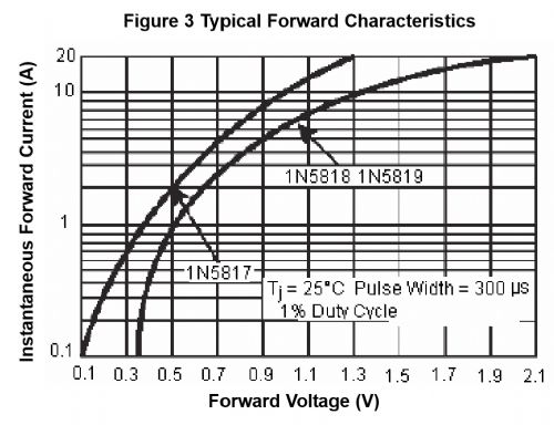
Regards, Mick Mick's uMite Stuff can be found >>> HERE (Kindly hosted by Dontronics) <<< |
||||
| robert.rozee Guru Joined: 31/12/2012 Location: New ZealandPosts: 2517 |
you could drop the ground and 3v3 pads on the right, shunt the micromite over into the free space and have expanded space for the regulators. i'm heading out of town this afternoon until the 22nd nov, and quite possibly won't have internet access during that time. will look forward to seeing how the ideas have developed when i get back! cheers, rob :-) |
||||
| Grogster Admin Group Joined: 31/12/2012 Location: New ZealandPosts: 9964 |
Have a nice "Holiday" or whatever it is going to be, Rob! 
@ Mick - We could drop the 5819 on the 3v3 output totally - that would get around the problem, so long as there was a clear label on the 3v3 bus side of things that this was an output only, and not an input. That's the only reason for the diode - to stop someone connecting power in to that point, which would be OK for the Micromite, but it would mean feeding 3v3 into the OUTPUT of the regulator, which I thought would not be a good idea....... Smoke makes things work. When the smoke gets out, it stops! |
||||
| bigmik Guru Joined: 20/06/2011 Location: AustraliaPosts: 2981 |
Grogster, Personally I think it unlikely that 3v3 would be `field connected' to those pins.. 3v3 power sources are not really that common in my experience but yes they need to be labelled.. Please take my comments in the vein they are offered as `constructive' Also please note that, unlike my wife, I do NOT know everything.. 
In fact, the more things I do, the less I seem to know. That is what the Forum is great for.. A valuable resource of Knowledge and members with a wide area of expertise.. Regards, Mick Mick's uMite Stuff can be found >>> HERE (Kindly hosted by Dontronics) <<< |
||||
| Grogster Admin Group Joined: 31/12/2012 Location: New ZealandPosts: 9964 |
Heh, heh - yeah, I take all comments as constructive criticism, and everything is taken under advisement. This does not automatically mean I will implement everything everyone says, but most ideas are good ones, so....
At the end of the day, as with most things, it is impossible to please everyone all of the time. I must tell you wife how you refer to her here..... Smoke makes things work. When the smoke gets out, it stops! |
||||
| Grogster Admin Group Joined: 31/12/2012 Location: New ZealandPosts: 9964 |
UPDATE: Have played with the layout, and now have DC socket on-board, and 5v regulator. I have had to go to SMD for some parts, but they are 1206 which is not too tricky to solder. If anyone is interested in this board, I could supply the boards with the SMD already soldered, leaving you only to assemble the rest of the through-hole parts. I have a ton of all the 1206 parts, which is one reason for designing them in. The other is lack of space. 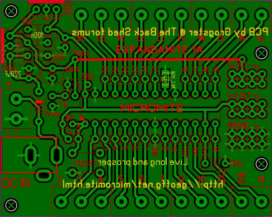
I have done away with the ICSP header at the suggestion of Rob. This was a good suggestion, as you have access to the programming pins on the t-blocks or headers anyway. Yes, you will have to wire up for programming, or just program the chip elsewhere and do a chip swap - either is easy, really. On the right of the board, there are now eight connection points via the headers, for 3v3, 5v and ground. These could be header sockets instead of pins, allowing you to plug in breadboard jumper wires etc. EDIT: Have got rid of all but one SMD part, which is a zero-ohm link. All standard thru-hole parts now, except for that one link. I am looking at ways to replace that. EDIT: Done. Replaced with wire-link top-side. I know that the aim is for no links at all, but.... PCB is now single-sided, and NO surface-mount stuff. All parts are thru-hole. EDIT: Whoops! Forgot Vcap. Will change that. Smoke makes things work. When the smoke gets out, it stops! |
||||
| MicroBlocks Guru Joined: 12/05/2012 Location: ThailandPosts: 2209 |
The mclr is missing on the t-blocks and I would not move pin one header 0.1" to the left. The power connections on the right are easier to use when the grounds are in the center. That will prevent the wires connected to them being entangled. Maybe do rows of power and ground to keep the wires close together and in the same orientation. Like: [code] 5 5 5 5 G G G G 3 3 3 3 G G G G [/code] Only one wire jumper is a great accomplishment.😃 Microblocks. Build with logic. |
||||
| Grogster Admin Group Joined: 31/12/2012 Location: New ZealandPosts: 9964 |
OK, how about this then: 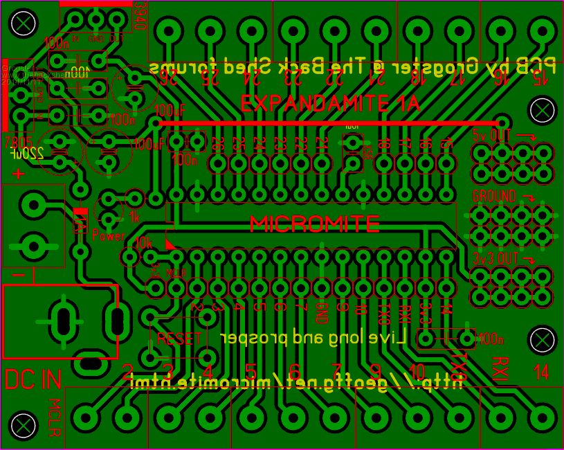
Smoke makes things work. When the smoke gets out, it stops! |
||||
centrex Guru Joined: 13/11/2011 Location: AustraliaPosts: 320 |
hi Grogster Very well done, will you be posting it as a 1 to 1 pdf file as requested by Atemega8 a few posts ago. For those who like to roll their own pcb a pdf would make it easy, unless of course you intend to get some manufactured for sale. For me you have just about covered it all except I2C but then as you say make up a special cable. Cliff Cliff |
||||
| The Back Shed's forum code is written, and hosted, in Australia. | © JAQ Software 2026 |
