
|
|
Forum Index : Microcontroller and PC projects : VideoMite 1A...
| Author | Message | ||||
bigmik Guru Joined: 20/06/2011 Location: AustraliaPosts: 2981 |
Hi Grogster, Are those two links above the 5V DC IN text? If so, you need to label which one does the USB power which one is external power. Mick Mick's uMite Stuff can be found >>> HERE (Kindly hosted by Dontronics) <<< |
||||
Grogster Admin Group Joined: 31/12/2012 Location: New ZealandPosts: 9975 |
They were diodes, but I have changed them to a 3-way jumper link arrangement. 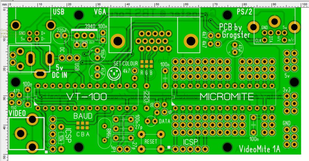
Annoyingly, you were right about the schotkky diodes' forward voltage-drop. I was assured that Schottky diodes only have a 0.1v voltage-drop, but when I actually looked up the datasheet for the diodes I have been using, the forward voltage-drop is actually 0.45v. 
That's still better then the 0.6v drop of 40xx diodes, but it is not the 0.1v I was told was the case with Schottky's. 
So, the onus is on the user to make sure the polarity is correct with the 5v DC connection. Smoke makes things work. When the smoke gets out, it stops! |
||||
| paceman Guru Joined: 07/10/2011 Location: AustraliaPosts: 1329 |
Looks like a plan view of a spaghetti pack Grogs  . . |
||||
| Grogster Admin Group Joined: 31/12/2012 Location: New ZealandPosts: 9975 |
Excellent - I like spaghetti, and was planning to make a bolognese tonight, but I don't think FR4 would make a nice flavour enhancement.  Smoke makes things work. When the smoke gets out, it stops! |
||||
| viscomjim Guru Joined: 08/01/2014 Location: United StatesPosts: 925 |
Grogster, I have to say, this is a very nice setup!!! I may need to get my hands on one or two!!! |
||||
| bigmik Guru Joined: 20/06/2011 Location: AustraliaPosts: 2981 |
Hi Grogster, I think links are better, I believe that the 1N5817 is actually closer to the 0.1v drop (according the the specs) but I have not tested them. I have only had experience with the more common 1N5819. As to polarity of 5VDC in, providing the way your design is for +ve on the `pin' and -ve on the barrel you should be OK as I have never seen a 5Vdc supply that is the other way round... (other voltages definitely...but not 5v). The T-Block or header yes they have to be careful of polarity, which is another point, your overlay doesnt (yet) show the polarity for those power input options. Mick PS.. Very nice work Grogs, I will have to get one from you. Mick Mick's uMite Stuff can be found >>> HERE (Kindly hosted by Dontronics) <<< |
||||
| Grogster Admin Group Joined: 31/12/2012 Location: New ZealandPosts: 9975 |
@ viscomjim & Mick - thanks. 
I will be getting a batch of PCB's done very soon, once I am happy with the final layout. As there are no SMD parts on this one, ALL components should be easy for anyone to source. @ Mick - yes, centre-positive DC connection - pretty standard. I will add text to that effect beside the socket and markings for the T-block and header. EDIT: Here we are then..... Top side: 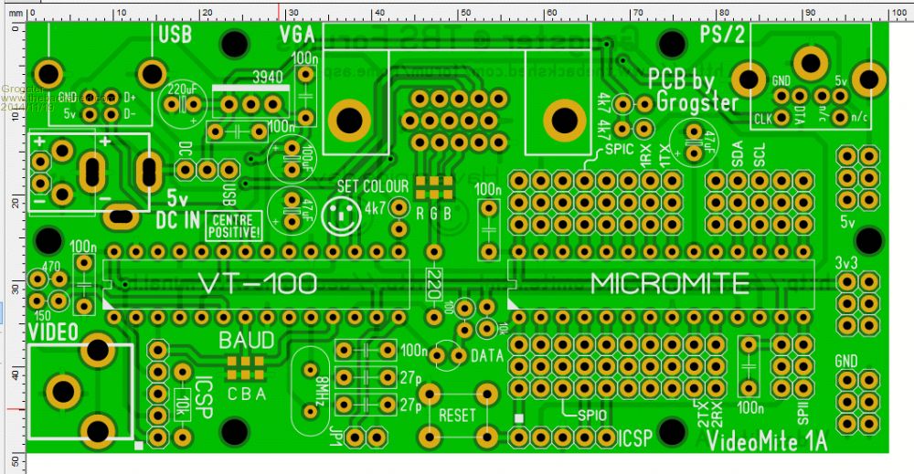
Bottom side: 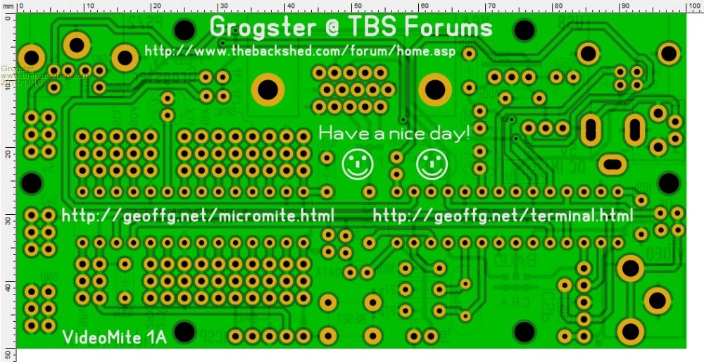
Smoke makes things work. When the smoke gets out, it stops! |
||||
| bigmik Guru Joined: 20/06/2011 Location: AustraliaPosts: 2981 |
Hey Grogs is that left hand smiley face on the `back side' ME? Minor Criticisms. If you can make the + and - a bit bigger font for power input it would be better. If you can move the USB from the jumper up and maybe r/a (with a line pointing to the pin if needed) then the CENTRE POSITIVE message can be level with 5vDC IN and the entire message enclosed in the BOX. Regards, Mick PS. Were you able to shave 0.5mm off the height to panelise for cost saving? Although on second thought that might not be necessary anyway 2 x 50mm boards with the vee groove down the centre would probably be ok anyway.. If you want me to create a border outline with cut outs gerber for you let me know. PPS. My second lot of boards arrived from Shenzhen today, the first lot took 14 days for postage, this lot took 16 days.. Not bad for the price compared to the expense they want for DHL. Regards, Mick Mick's uMite Stuff can be found >>> HERE (Kindly hosted by Dontronics) <<< |
||||
| Grogster Admin Group Joined: 31/12/2012 Location: New ZealandPosts: 9975 |
It can be you, if you want it to be. 
Yep, I can do that - will post updated image soon. No I have not squeezed it yet, but I will. Shenzhen info page says you have to have 5mm around the edge for panelized boards anyway, which would take us up into the 15x15 size. I think I will just get them standard as 10x5's @ ~$12 for 10 - still a pretty good price. I will just get two batches to have 20 boards. No point in stocking up on boards I may well not be able to move.
Yes, that's not bad. Is that 14 & 16 days from the day they told you they were shipped, or does that also include the production time? Smoke makes things work. When the smoke gets out, it stops! |
||||
| bigmik Guru Joined: 20/06/2011 Location: AustraliaPosts: 2981 |
Grogs, I dont think that is the case with the 5mm edge.. The order that arrived today was a 2 x 2 panelised MuPs with 0.5mm gaps that takes the panel to 86.5 x 99.5mm. I believe the edge is only needed if there isnt mounting holes of at least 2mm dia (based on other companies I have dealt with). I dont think they treat my boards as `panels' I think their panels are when they separate them into individual boards.. I would upload the artwork and let them reply if there is any issue. As to total time here is the time frame that happened on my last order. Order placed on 29/10 Shipped 3/11 Arrived 19/11 (21 days total turn around) Take into account that I chose `snail mail' shipping .. in this case only $9US Mick Mick's uMite Stuff can be found >>> HERE (Kindly hosted by Dontronics) <<< |
||||
| Grogster Admin Group Joined: 31/12/2012 Location: New ZealandPosts: 9975 |
Thanks for that turn-around info. Here is the image with the changes you suggested: EDIT: I have added two jumpers - TXJ and RXJ. With these jumpers in place, the uM is routed to the VT100. If you remove them, you can then use lower pins of those jumpers, and the GND from the adjacent ICSP, as a serial connection to the VT100 if you want to use it separate from the on-board Micromite in testing other hook-ups. Likewise, you can remove these same jumpers, and then tap into the Micromite console, without the VT100 upsetting the mix by being permanently connected. The normal arrangement, would be jumpers on these two points(and transfer code to the Micromite via the VT100's USB interface), but it gives you the flexibility to alter things depending on what you happen to be doing. 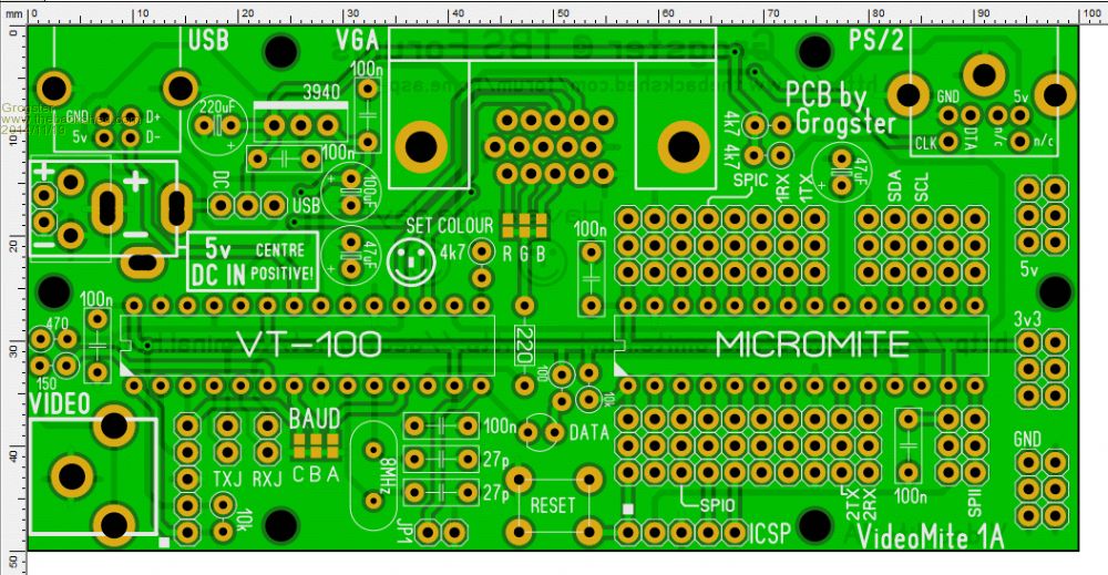
Smoke makes things work. When the smoke gets out, it stops! |
||||
| paceman Guru Joined: 07/10/2011 Location: AustraliaPosts: 1329 |
Grogs - if you turn that TXJ jumper around 90 deg you might have room for the 5v adapter protection resistor if someone plugs into the Micromite direct, i.e. with the jumper out. (I assume that's the Rx into the Micromite). Greg |
||||
| Grogster Admin Group Joined: 31/12/2012 Location: New ZealandPosts: 9975 |
What value is that? 10k? In series with the uM RXD, correct? EDIT: I have assumed this resistor is 10k, but it can be anything. I have it installed on the bottom copper layer. Standard resistor. In series with the uM RXD. Smoke makes things work. When the smoke gets out, it stops! |
||||
| paceman Guru Joined: 07/10/2011 Location: AustraliaPosts: 1329 |
No, 1K not 10K. Yep, in series to uMite RX. It might save a few puzzled, disgruntled users in future! |
||||
| Grogster Admin Group Joined: 31/12/2012 Location: New ZealandPosts: 9975 |
OK, 1k. It shall be so labelled.
Is the 1k in series with the uM RXD still OK to be there for 3v3 operation? I would prefer to be able to leave it there permanently... Smoke makes things work. When the smoke gets out, it stops! |
||||
| paceman Guru Joined: 07/10/2011 Location: AustraliaPosts: 1329 |
I use the 1K permanently in with a 3.3v adapter and it works fine. I just checked Mick's MUP V2 and he has a jumper to remove it you want to, when using a 3.3v one. I don't think you need to do that but it might be best to check with him. Greg |
||||
| bigmik Guru Joined: 20/06/2011 Location: AustraliaPosts: 2981 |
Hi Greg, I have found the same, that it still works at 3v3 with the resistor in but I suppose that there is no guarantee that all USB-TTL converters will work with the resistor there. Mick Mick's uMite Stuff can be found >>> HERE (Kindly hosted by Dontronics) <<< |
||||
| Grogster Admin Group Joined: 31/12/2012 Location: New ZealandPosts: 9975 |
@ Greg & Mick - I will include the resistor by default, and add solder blob pads to allow you to short it out if you need to. That should cover both possibilities. Smoke makes things work. When the smoke gets out, it stops! |
||||
| bigmik Guru Joined: 20/06/2011 Location: AustraliaPosts: 2981 |
Perfect!! Job well done  Mick's uMite Stuff can be found >>> HERE (Kindly hosted by Dontronics) <<< |
||||
| Grogster Admin Group Joined: 31/12/2012 Location: New ZealandPosts: 9975 |
OK, here you are then. This is the board I will be ordering tomorrow. TOP LAYER: 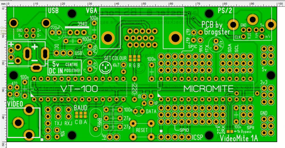
BOTTOM LAYER: 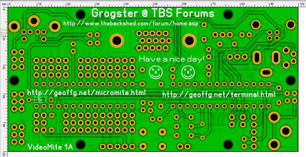
Smoke makes things work. When the smoke gets out, it stops! |
||||
| The Back Shed's forum code is written, and hosted, in Australia. | © JAQ Software 2026 |
