
|
|
Forum Index : Microcontroller and PC projects : Autotrax DEX Libraries
| Author | Message | ||||
bigmik Guru Joined: 20/06/2011 Location: AustraliaPosts: 2981 |
Lads, Just as an example of the internal router I have used my first effort of doing a PCB using AUTOTRAX DEX (ok 2nd as this is my Ver 2 MuP) I have removed the copper pours for clarity. Here is the board unrouted and showing the nets loaded. 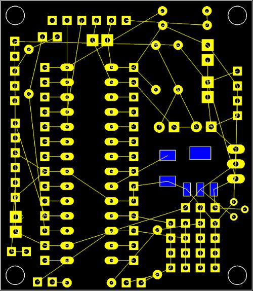
Here is how DEX routed the PCB 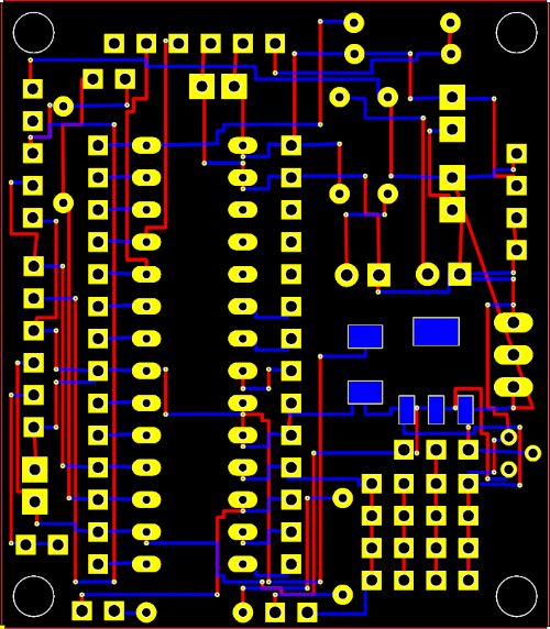
After maybe 2 hours of work I have cleared it up a fair bit and this is what I ended up with.. No vias at all. I now try to make every track on a 45 or 90 degree angle and avoid 90 degree bends, but this was my earlier efforts. 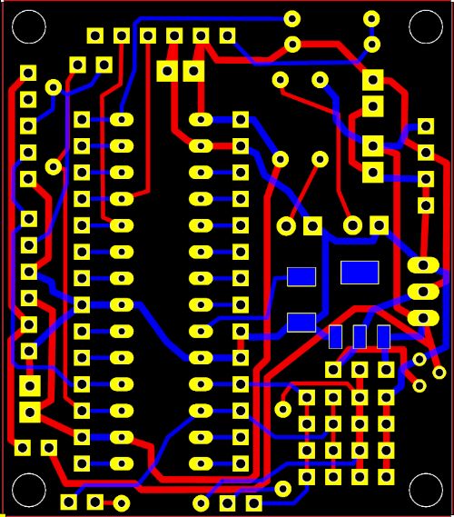
Regards, Mick Mick's uMite Stuff can be found >>> HERE (Kindly hosted by Dontronics) <<< |
||||
| bigmik Guru Joined: 20/06/2011 Location: AustraliaPosts: 2981 |
Lads, Here is a pair of simple batch files to create standard names for gerber files from AUTOTRAX DEX standard names. It consists of two batch files. GO.BAT Edit the 2nd string inside quotes currently NanoMite Motherboard to whatever you want to call your board. and Rename Gerbers.Bat The grunt part of the copy process no need to edit. 2015-01-25_004436_Rename_Gerbers.zip Regards, Mick Mick's uMite Stuff can be found >>> HERE (Kindly hosted by Dontronics) <<< |
||||
| WhiteWizzard Guru Joined: 05/04/2013 Location: United KingdomPosts: 2991 |
THANKS to all of you regarding comments about AutoTrax - looking like a good design tool. I have been busy watching numerous tutorial videos while I've been away this weekend; and now just have two more questions: 1> Can components be placed on both sides of the PCB? 2> Can you panelise a small PCB onto a 'slab' for a fab-house? I assume the answer to both of these is 'yes' if BigMicks NanoMite was designed using this software?!!? Also have any of you purchased an optional AutoRouter that works well with this package? Thanks again for any help . . . . WW |
||||
| bigmik Guru Joined: 20/06/2011 Location: AustraliaPosts: 2981 |
Ww, Yes to both points... Initially a part is placed on the top surface, just click it then select property panel and tell it to jump to the bottom layer. Panelising (the same board) is very easy.. In the cam settings select the number of horizontal boards and vertical boards and define a gap, I generally use 0.02" as my gap. I would like to know if we can panelise two different boards, I don't think so but you never know. Regards, Mick Mick's uMite Stuff can be found >>> HERE (Kindly hosted by Dontronics) <<< |
||||
| WhiteWizzard Guru Joined: 05/04/2013 Location: United KingdomPosts: 2991 |
Thanks Mick - that is what I was hoping you were going to confirm! Am busy now installing the software on my iMac; under Windows (via Parallels). Not sure how the functions using right click will work out but it will be good to get this all working on a nice big display. If I wanted to add 3d parts to your library can that be done? It would be nice to see 3D images of the finished PCB populated; and even nicer to 3D print it to ensure it fits into the casing. WW |
||||
| bigmik Guru Joined: 20/06/2011 Location: AustraliaPosts: 2981 |
Ww, Yes of course you can add/edit them... I just didn't bother as I don't use the 3d side of the package, or the simulation circuit for that matter.. I do like the idea but it isn't critical to me... Maybe I need to revisit 3d. If you add them please share and we can all benefit. Also some if the parts from my library are from scratch ... No 3d some are ones I copied from the existing Libs and edited to suit my purposes, these could have weird 3d packages as I may have made a ssop footprint from a dip part etc... But of course every and any part can be edited, in fact I prefer to edit a similar part than create from scratch, and of course 3d is one part that can be editted.. Iliya, the author , has many video clips and the forum will probably answer your questions if you still have any. Mick Mick's uMite Stuff can be found >>> HERE (Kindly hosted by Dontronics) <<< |
||||
| bigmik Guru Joined: 20/06/2011 Location: AustraliaPosts: 2981 |
Hi All, I have been reconsidering my thoughts on 3D and decided to create my parts with 3D models. I have started with LEDs and have created (editted from existing parts to suit my requirements) these if anyone is interested. 2015-02-03_091452_LEDs.zip The following are examples of the LEDs, 5 colours (Blue Green Red White Yellow) and 3mm and 5mm packages 3D Examples 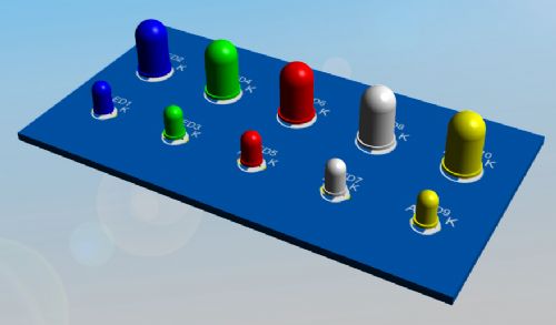
Overlay Examples 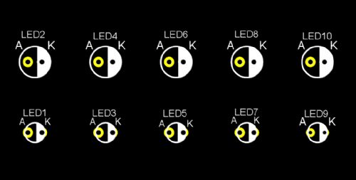
Schematic 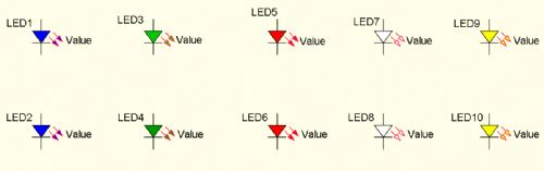
ENJOY!! Regards, Mick EDIT*** If anyone knows how to put a flat on the cathode in the 3D drawing please let me know how and I will add them. Mik Mick's uMite Stuff can be found >>> HERE (Kindly hosted by Dontronics) <<< |
||||
| WhiteWizzard Guru Joined: 05/04/2013 Location: United KingdomPosts: 2991 |
I'm going to have to buy a multicolour 3-D printer now  |
||||
| Zonker Guru Joined: 18/08/2012 Location: United StatesPosts: 772 |
Nice Mick..! Where is a good place to get the 3-D models you are using..? Looks good... This is one more thing I cant seem to find enough time for... Keep up the excellent work..! |
||||
| bigmik Guru Joined: 20/06/2011 Location: AustraliaPosts: 2981 |
Thanks Zonker, I intend to redo my library of parts to add the 3d images.. You can download images but aparrently these add a fair bit of size (Kb) to the parts... These ones are generated by three geometric parts , a sphere, tall cylinder and a short cylinder . The images and schematic are on parts that are already in the library but I hated the overlays and the colour of the 3d was translucent which, albeit sort of like the real parts, I didn't like so I edited them. They were also for 3mm LEDs so I also editted them to create 5mm ones.. If there is interest I can also do 8mm and 10mm ones. Mick Mick's uMite Stuff can be found >>> HERE (Kindly hosted by Dontronics) <<< |
||||
| vasi Guru Joined: 23/03/2007 Location: RomaniaPosts: 1697 |
He he, nice to have, right? 
3D board in DipTrace with KiCAD 3D objects - the advantage of a common file format - maybe is the same for AutoTRAX, can someone check this? 
And strictly artistic, IMO nothing beats Eagle+Eagle3D+POVray team regarding the rendering result: 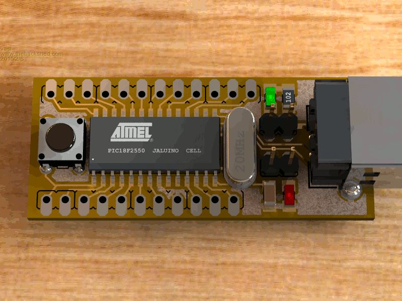
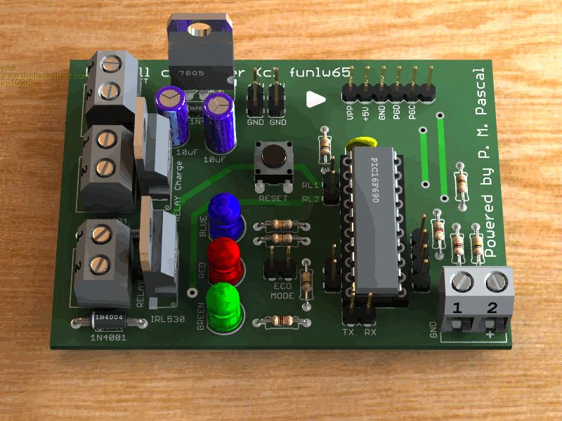
The disadvantage is that it lacks the integration and is difficult to use it. And to be honest, is not an attribute of Eagle as is for AutoTRAX, KiCAD, DipTrace, etc. Anyway, nice to have the 3D object of any components you use. Hobbit name: Togo Toadfoot of Frogmorton Elvish name: Mablung Miriel Beyound Arduino Lang |
||||
| bigmik Guru Joined: 20/06/2011 Location: AustraliaPosts: 2981 |
Hi Vasi, Some of those examples are certainly brilliant WOW.. I really couldn't have cared less for 3D when I started with DEX but I am slowly coming around to it.. DEX can import 3D files in .STL format but there is no colour the preferred format is .XGL which has colour. DEX can export 3D to .STL, Collada and Active3D formats. The LEDs shown in my example I created from a short cylinder (for the base) a larger cylinder for the body and a sphere and adjusted them till they sat on top of each other. Regards, Mick PS. Playing with 3D models (creating/editting them) is a right royal pain in the A$$.. I really dont find DEX very user friendly when it comes to 3D manipulation but once the 3D model is there it is just an automatic process the 3D is there, use it or not. Mik Mick's uMite Stuff can be found >>> HERE (Kindly hosted by Dontronics) <<< |
||||
| smudge Newbie Joined: 04/12/2014 Location: United KingdomPosts: 16 |
Hi After reading this thread I loaded Autotrax onto my Mac book Pro using the "virtual box" virtual machine which seems to run it well. I would agree it is a steep learning curve but I seem to be making progress. I'm now working on the routing stage and would agree with Mik about the auto-routing. Prior to this I had tried Design Spark and Express PCB and autotrax is definitely the be of the three. John |
||||
| viscomjim Guru Joined: 08/01/2014 Location: United StatesPosts: 925 |
Hi Smudge, Since you just started with DEX, get a good circuit designed and try the Electra auto router trial that is available in DEX I think for 30 days. It is really something and fast to, fun to watch how it does its thing. I am tempted to get this but I think its about $450.00 or so. Iilya was talking on the forum that he is working on a better autorouter for DEX so I am holding out a bit longer. Welcome to the forum!!! |
||||
| smudge Newbie Joined: 04/12/2014 Location: United KingdomPosts: 16 |
Hi Viscomjim Thanks for the advice, I'm sticking to manual routing at the moment rather than the Dex router but I seem to have problems with some nets. I can route the track by say dragging and I get to the green arrow but when i let go of the mouse button the track disappears and the net reappears, I must be doing something wrong but I don't know what. Some nets route fine though. I'll take your advice and try the Electra but at $450 it's a bit pricey! John |
||||
| viscomjim Guru Joined: 08/01/2014 Location: United StatesPosts: 925 |
smudge, hopefully it is not a problem with the virtual box you are using. I am using parallels, but the author only recommends VMware fusion as mentioned here. I think this was written a while back and newer versions of all the virtual machines have changed since, so maybe why I am having luck with parallels (newest version of OSX and parallels). HERE is my very first board with DEX. |
||||
| bigmik Guru Joined: 20/06/2011 Location: AustraliaPosts: 2981 |
Lads, I have redone Some SIP headers for DEX to include 3D objects. As per usual these were done to suit my needs and preferences so they may not suit yours.. I have included in this pack 2pin, 3pin, 4pin, 5pin, 6pin and 14pin both Male and Female. I will add more as time permits and I will do dual row headers as well but at this stage it is only the headers that I use on my boards that I have redone. 2015-02-14_015033_Headers_SIP.zip 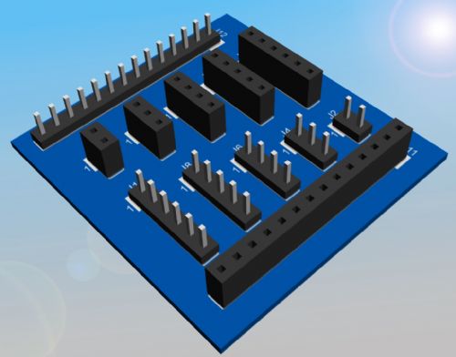
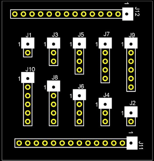
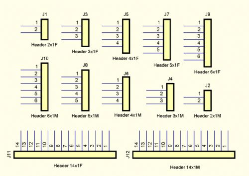
All of the Pin1's are actually a square pad (can't be seen under the white silkscreen) but of course you can change these on the fly if you don't want that. Regards, Mick Mick's uMite Stuff can be found >>> HERE (Kindly hosted by Dontronics) <<< |
||||
| viscomjim Guru Joined: 08/01/2014 Location: United StatesPosts: 925 |
Thanks Mik, these are great. The ones in DEX have small holes and this almost bit me in the A$$. These are a welcome addition!!!!! |
||||
| bigmik Guru Joined: 20/06/2011 Location: AustraliaPosts: 2981 |
Thanks Jim, I have done a few more, but I will keep them until I get a few more done. I have started on the dual row pins, I have a VGA connector, PS2 Connector and a BC337 all with reasonably good 3D models. One of the reason I am `re-inventing the horse' is that the hole sizes cannot be trusted and some of the overlays are pretty bad (square outline for a to-92 case for instance). I don't want to have to check every part each time I use it.. so I am making my own army of them. Regards, Mick Mick's uMite Stuff can be found >>> HERE (Kindly hosted by Dontronics) <<< |
||||
| viscomjim Guru Joined: 08/01/2014 Location: United StatesPosts: 925 |
Your efforts will go to good use (at least by me) I am sure! Thanks again!!! |
||||
| The Back Shed's forum code is written, and hosted, in Australia. | © JAQ Software 2026 |
