
|
|
Forum Index : Microcontroller and PC projects : Latching relay question....
| Author | Message | ||||
redrok Senior Member Joined: 15/09/2014 Location: United StatesPosts: 209 |
Hi larny;"Not quite" right because your calculations were based on a supply of 12V whereas Grogster's circuit was based on a 5V supply and used a 4.5V Panasonic relay with a coil resistance of 135ohms. I further showed that all values of resistance pairs, in this type of circuit, never need snubber diodes because the kickback voltage can never go below ground nor greater than 2 times the supply, 10V in this case. redrok |
||||
Grogster Admin Group Joined: 31/12/2012 Location: New ZealandPosts: 9975 |
Hi folks. 
Nice technical discussion going on here - interesting reading. I kept the top diodes(across the resistors), but dropped the bottom diodes(across the 337's C-E's) Based on what is being written here, looks like I may be able to simply not install the diodes either. Incidentally, in my prototype test of this circuit, the on pulse current is much higher then the calculations are showing it to be - around 150mA or so. Using my schematic at the top of this page, lets look at why this is: Assuming that you apply 3v3 to the OPEN line, then T2 switches on, drawing current through the relay coil, latching it into the desired position. However, at the same time this happens, a large current can flow via R2 to ground via T2 being on. The exact same thing happens with the CLOSE side of the relay, so it IS a thirsty circuit, and not really very efficient due to the amount of current wasted during switching. That having been said, I have had very successful and reliable relay switching with a pulse of only 5ms, and as you are not supposed to leave juice on the control lines anyway..... The problem with this circuit, is if you FORGET to just use the PULSE command to trip the relay one way or the other, and accidentally leave the I/O pin high on one of the two lines - it will burn out the resistor given a little time. But again - this circuit is, by design, supposed to be PULSE-driven, not continuously driven. Win some, lose some. Smoke makes things work. When the smoke gets out, it stops! |
||||
| larny Guru Joined: 31/10/2011 Location: AustraliaPosts: 349 |
Thanks redrok, I thought you were referring to the Gerry's comment which is correct. I did not notice that the relay used by the OP is a 5 Volt one. So I assumed 12 Volt. In general, the collector voltage does not exceed 2 Vcc or go below the saturation voltage - as you said. |
||||
| larny Guru Joined: 31/10/2011 Location: AustraliaPosts: 349 |
Grogster, As redrok & I have shown, you don't need any diodes. |
||||
| redrok Senior Member Joined: 15/09/2014 Location: United StatesPosts: 209 |
Hi Grogster;Hmmmm, that is a bit different calculation, lets see: The coil ON current will still be: 5V / (135ohm + 47ohm) = 27.5mA Now the peak current will be 27.5mA across the 1 resistor will be: 27.5ma * (47ohm * 1) = 1.29V The driven transistor when turned off will have: Since there is now a snubber diode which will have about 0.7V across it. 5V + 0.7V = 5.7V or so. And the passive transistor will still have: 5V - 1.29V = 3.71V And after the current collapses they will both have 5V.That is correct. There is an advantage in not using the high side snubbers in this circuit. Snubber diodes reduce the series resistance for disipating the energy stored in the inductor. The lower the resistance the longer it takes to dissipate the energy. No snubbers means faster dissipation in this circuit.Quite true. The currents we were calculating was only the coil current and kickback voltages. That load resister conducts a lot more current than the coil.That would be a problem if this wasn't a latching relay.In this case the 47ohm will dissipate: 5V^2 / 47ohm = 0.54 Watts.redrok |
||||
| Grogster Admin Group Joined: 31/12/2012 Location: New ZealandPosts: 9975 |
@ larny - OK. My PCB design has the diodes, but I can just leave them out... Acknowledged. I will leave out the high-side diodes. They are on the PCB pattern, but I just won't fit them. As they are in parallel with the load resistors, it will not affect the circuit.
You seem to know your electronic theory well - are you a teacher or something? Smoke makes things work. When the smoke gets out, it stops! |
||||
| redrok Senior Member Joined: 15/09/2014 Location: United StatesPosts: 209 |
Hi Grogster;You could populate these locations with resistors, use 4 91ohm resistors instead of 2 47ohm resistors so the power dissipation is spread out more. BTW, there is a component not mentioned here, the capacitor. Since the 5mS current pulse is a bit high at: ( 5V / 47ohm ) + ( 5V / ( 135ohm + 47ohm ) = 134mA And lets assume the voltage drop is limited to 0.5V deltaA * deltaS / deltaV = C in farads 134mA * 5mS / 0.5V = 1340uF Assuming all the current is coming from the capacitor. In the real world some of the current can come from the regulator which can reduce the capacitor value proportionately. Yes, this seems like a big capacitor but that's the tradeoff for not using an H-Bridge where the capacitor would be: 37mA * 5mS / 0.5V = 370uF You may be interested in a simple H-Bridge I invented. This is ideal for use with a micro.No, just a circuit designer. I worked at Unisys for 37 years. Full disclosure, I do not have an engineering ticket, mostly self taught. I love circuit design though. redrok |
||||
| Grogster Admin Group Joined: 31/12/2012 Location: New ZealandPosts: 9975 |
So, are you saying there should be a cap in the area of 2200uF on the supply line on this module? Perhaps you could clarify for me, the capacitor issue a little more. 
I will have a play to see how short a pulse I can get this down to, and still reliably operate the relays. I can probably do better then 5ms. If I can get it down to 1ms, then the 220uF cap I have on the board supply is probably gonna fit well, based on your example calculations.... EDIT: Correction - I don't have any cap on the supply to this board - did not think it was needed at the time. Smoke makes things work. When the smoke gets out, it stops! |
||||
| redrok Senior Member Joined: 15/09/2014 Location: United StatesPosts: 209 |
Hi Grogster; What is the current capability of the 5V regulator. Actually what is the excess current capability of the regulator after powering everything else. If the excess is 150mA or so you wouldn't need the large capacitor to supply the pulse current. You really should have a reasonably large filter cap anyway. I always have at least a 100uF cap. redrok |
||||
| Grogster Admin Group Joined: 31/12/2012 Location: New ZealandPosts: 9975 |
Okey dokey. I normally put 220uF on the input of just about everything, but ironically, did not on this board, as I did not think it would care about a smooth supply rail - completely forgot about surge current of this arrangement. The regulators are usually 1703-33's, which are good for up to 250mA. If not them, then I tend to use 3940 linears, which are good for up to 1A. There is always plenty of decoupling caps around my PSU stages. Thanks for your comments - very insightful. Smoke makes things work. When the smoke gets out, it stops! |
||||
| redrok Senior Member Joined: 15/09/2014 Location: United StatesPosts: 209 |
Hi Grogster;Don't forget the required 1uF close to the MCP1703-33regulator output. And the LM3940 requires .47uF on the input and at least 33uF on the output. Both of these are "High Performance" regulators and require special precautions when using them. Read the datasheet carefully especially with regard to the capacitor ESR ratings. redrok |
||||
| Grogster Admin Group Joined: 31/12/2012 Location: New ZealandPosts: 9975 |
Yep, I use 1uF X5R MLC's within 1mm of the input and output pins. I also have 100n MLC's on input and output too. I have never had a problem with the 1703 series - yet - and I have used hundreds of them now. Smoke makes things work. When the smoke gets out, it stops! |
||||
| redrok Senior Member Joined: 15/09/2014 Location: United StatesPosts: 209 |
Hi Grogster; I know your circuitry is already designed but I would be remiss if I didn't show a very nice all MOSFET H-Bridge: 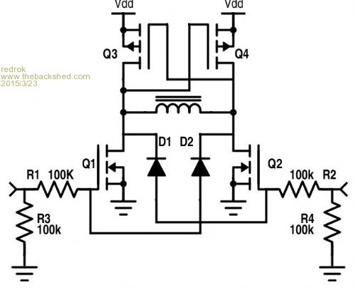
The high side DMP2215L-7 MOSFET would work well at 3.3V. The 2 diodes guarantee minimal shoot through in case both MOSFETs are enabled at the same time. When running it at higher voltages make sure the high side MOSFET maximum gate voltage is not exceeded. redrok |
||||
| Grogster Admin Group Joined: 31/12/2012 Location: New ZealandPosts: 9975 |
Cool. 
Printed for future reference. Smoke makes things work. When the smoke gets out, it stops! |
||||
| The Back Shed's forum code is written, and hosted, in Australia. | © JAQ Software 2026 |
