
|
|
Forum Index : Microcontroller and PC projects : MAXIMITE and BRBL ARDUINO
| Author | Message | ||||
| PeterB Guru Joined: 05/02/2015 Location: AustraliaPosts: 669 |
G'Day Mick GRBL is a program to drive a milling machine and can be installed onto an Arduino. The idea is then to plug the Arduino into your PC via USB and drive your mill anyway you like. I have that part working, I can type GCode into TERATERM and see step and direction signals on the Arduino pins. So then I bought a MAXIMITE with the idea of using that to send GCode via a FTDI device on COM1. As I said in an earlier post, I have never really understood USB and the result is that my beaut idea doesn't work. I suspect it's to do with the COM1 - FTDI not being a "real" USB port. Thanks for your interest. Peter |
||||
TassyJim Guru Joined: 07/08/2011 Location: AustraliaPosts: 6538 |
I don't have any experience with Arduino but I think you need to change your Arduino program to listen on a serial port instead of (or as well as) the USB You can send code out the micromite com ports OK but you cannot connect them to a USB device. The micromite/maximite can not be a USB host. Once you have your program on the Arduino listening on it's serial port, we might have to do some tweaking (such as invert signals and allow for different voltages). You should be able to connect the micromite to your PC using the FTDI adapter and the Arduino to the PC using it's USB. Each device can communicate with a different terminal program at the same time. You could then experiment sending data from the PC to the micromite and on to the Arduino and see the data back on your PC. Jim VK7JH MMedit |
||||
| PeterB Guru Joined: 05/02/2015 Location: AustraliaPosts: 669 |
G'Day Jim People are popping up in all directions. I think you have hit the nail on the head with "the MM can not be a USB host". I don't want to start modifying GRBL. That way lies madness. I was just trying to make a simple system but seem to have failed (again) 
Peter |
||||
BobD Guru Joined: 07/12/2011 Location: AustraliaPosts: 935 |
I'm with Mick on this one. I still can't figure out how it is all connected. |
||||
| PeterB Guru Joined: 05/02/2015 Location: AustraliaPosts: 669 |
G'Day Bob (what have I started?) I have a MAXIMITE with a FTDI device connected to COM1. The MM has a program that generates GCode and squirts it out COM1 so now I have a USB port with GCode pouring out the end. If I plug that USB port into my PC, I can see the GCode on TERATERM. I also have an Arduino with a very large program called GRBL installed. GRBL accepts GCode and converts it to step and direction signal. If I connect that Arduino to my PC I can drive the Arduino step & direction pins from TERATERM. Both ends work, it's the bit in the middle, the USB. Arduino works from a host and MAXIMITE cannot be a host. I think that is the problem. I think USB can work in 2 ways. Full (CDC?) or simple. I'm not sure about this and I would rather not spend my remaining years working it out. But it is fun. Peter |
||||
| BobD Guru Joined: 07/12/2011 Location: AustraliaPosts: 935 |
Peter The FTDI usb needs to be initialised before use. A PC can do that but a Maximite and an Arduino probably can't act as a usb host. Also, in this case, the FTDI usb is not even connected to the Maximite. You are connecting the FTDI serial pins to the MM and expecting the MM to initialise the usb. It's not going to happen. You didn't say how the Arduino was connected to the PC. It may not be important anymore but if it is to the Arduino serial pins then why don't you go MM serial to Arduino serial? Please correct me if I have misunderstood the connections. Mick asked for a diagram and that would have eliminated any confusion. Bob |
||||
| PeterB Guru Joined: 05/02/2015 Location: AustraliaPosts: 669 |
I tried to attach a drawing but had problems. The MAXIMITE connects to the FTDI serial pins and the FTDI can then communicate with a PC and TERATERM for example over a USB cable. Using that setup, I can see GCode generated by the MM on TERATERM. I can connect a PC to the Arduino running GRBL and drive the Arduino pins from TERATERM. However, in the final form, the PC does not connect to the Arduino. In fact the PC is switched OFF. The MM uses the FTDI on COM1 to send GCode over USB to the Arduino which then drives a milling machine via it's I/O pins. It all seemed so simple at the time. |
||||
| TassyJim Guru Joined: 07/08/2011 Location: AustraliaPosts: 6538 |
Both the MM (with the FTDI adapter) and the Arduino are USB Slaves. You cannot connect two USB slaves together like you are trying to do. One of the devices has to be a USB master. (Slave and Master are not the correct terminology for USB but the principle is correct) Getting rid of the USB on the maximite is easy. You need to find out if it is feasible to do so on the Arduino. Jim VK7JH MMedit |
||||
| PeterB Guru Joined: 05/02/2015 Location: AustraliaPosts: 669 |
Thanks Jim I agree. I don't want to get into the GRBL software in order to use serial, I2C, wet string etc. so I think it is a lost cause. I am surprised at how many people don't understand USB, I thought I was the only one. Peter |
||||
bigmik Guru Joined: 20/06/2011 Location: AustraliaPosts: 2981 |
Hi Peter, Aha!!, It is as I expected... you are trying to use the FTDI board like a converter between USB and Serial TTL That wont work exactly that way. Which Arduino board are you using? It may be possible that it actually has a FTDI chip or a similar chip that is a serial to TTL converter onboard in which case we should be able to disable it and just go TTL to TTL.. Maybe not if the particular board you run is using inbuilt USB pins. More information is required at this stage. Else maybe the DM (DuinoMite using the `forked' DM firmware) as at least one version of DMBasic supported USB OTG and it may be able to do as you want but you wont have all the niceties of the current flavour of MMBasic.. I will try to loacate some more info if that is an option but lets work out what your Arduino board actually is first eh? Regards, Mick Mick's uMite Stuff can be found >>> HERE (Kindly hosted by Dontronics) <<< |
||||
| PeterB Guru Joined: 05/02/2015 Location: AustraliaPosts: 669 |
G'Day Mick I have it on a DUEMILANOVE and a DCcduino uno. I I can't use a FTDI as a converter between USB and serial TTL what can it do? Peter |
||||
| bigmik Guru Joined: 20/06/2011 Location: AustraliaPosts: 2981 |
Gday Peter, Do not despair (yet) I searched for Duemilanove and got this page Link If that is similar to yours then it looks simple enough. The Duem... module has an onboard FT232RL chip for its USB interface so you should be able to isolate the TTL out put from the FT232RL chip to the CPU and feed the CPU directly with the TTL output of the Maximite Looking at this circuit: Duemilanove cct And this section 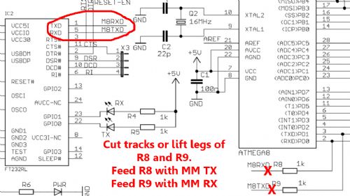
Either cut the tracks as shown with red X or lift the legs of R8 and R9 that go to the FT232RL chip (circled) and feed these lifted legs with the Maximite RX/TX (TTL level) pins. Note, you may need to go to the otherside of R8 due to MM only being 3v3.. try it Of course you will need a GND connection as well. Regards, Mick Mick's uMite Stuff can be found >>> HERE (Kindly hosted by Dontronics) <<< |
||||
| PeterB Guru Joined: 05/02/2015 Location: AustraliaPosts: 669 |
G'Day Mick I have just had a VERY GOOD IDEA If I load GRBL onto an ARDUINO PRO I don't have to deal with the FTDI chip because it hasn't got one. Perhaps all is not lost after all. Peter |
||||
| WhiteWizzard Guru Joined: 05/04/2013 Location: United KingdomPosts: 2991 |
Amazing, 24hrs later and we have lots more input 
Going back to my last post, we need to link the MM and Arduino directly via a serial connection. Thanks to Mick we can now see that no Arduino code needs changing (which was your fear) as the serial connections for the Arduino that we require are available with the aid of a soldering iron. Not 100% convinced you need to cut tracks though. Personally I would just solder a wire onto the MBTXD resistor for now - see below . . . One word of warning - IF you do have the version of unit as in Mick's post, you can't necessarily go by the PCB silkscreen on your unit and look for R9 (ignore the other signal - R8, as I don't think you need it). IF your unit is a 'clone' then there is a very good chance that the required resistor (R9 in the circuit diagram) will be labelled as something else on your unit. So with your unit, I would go to the FTDI chip (FT232RL or similar - assuming it has one!!) and follow back from Pin 5 ensuring it passes through a resistor (the ones labelled R9 in the circuit diagram above). Make sure that the track traces back to the Atmega to Pin 3 as a sense check. Then the FTDI pin 5 (MBTXD in circuit diagram) I would simply solder a small wire onto the FTDI side of the resistor. All of this is just to ensure you have the correct connection from the Arduino (the Arduino Tx line). This is then connected to the MM COM1 Rx line. Finally take a ground from each unit and simply connect together - result is just two interconnections JOB DONE
Please don't think this is too much hard work - it is easy, no tracks are cut, and it will result in what you wanted. Also as I previously mentioned, you may just need to make some MM code mods to deal with CR/LF issues but hopefully you have enough now to try. Please feedback your progress as you have a larger audience now 
Good luck . . . WW |
||||
| JohnS Guru Joined: 18/11/2011 Location: United KingdomPosts: 4335 |
bigmik is right in concept, I agree. Maybe the way to get one's brain around it is to think that it's the PC that needs USB because it hasn't got a serial port. Neither the MM nor Arduino need USB except due to the PC so to connect 'em together you want to bypass the USB parts. I think you may need to cut tracks / remove USB-serial chips because to drive serial-serial between the 2 boards you don't want to be fighting whatever level the USB-serial chips are outputting. If you'd had a 'mite with a USB-serial that was off board and an Arduino likewise then this would be so simple - just connect the 'mite to Arduino leaving the off board USB-serial devices disconnected (or plugged into the PC doing nothing). (You'd have to worry about the Arduino being 5V logic and 'mite 3V3 but the series resistor previously mentioned is enough to let the 'mite cope.) John |
||||
| WhiteWizzard Guru Joined: 05/04/2013 Location: United KingdomPosts: 2991 |
Guys, you won't need to cut any tracks as the MM is just needing to receive GCode (unless there are unmentioned other requirements from Peter). This also means there is no contention with the serial connection. |
||||
| bigmik Guru Joined: 20/06/2011 Location: AustraliaPosts: 2981 |
G'day peter, If the software runs fine on another board that uses TTL serial instead of USB then that would be the easiest and probably best solution. Just connect your MaxiMite to the new arduino board via TTL serial.. Be mindful that as the MM. Is 3v3 that whilst you can put MM TX into Arduino RX with no issues you will need a 1k resistor in series with the Arduino TX and MM RX. If it all works out ok and you don't need the keyboard and video of the MM you may want to use a micromite instead.. ** warning cheap plug inserted ** If interested look at the link in my signature below and look at my MuP board for one of many options available to you. Regards, Mick Mick's uMite Stuff can be found >>> HERE (Kindly hosted by Dontronics) <<< |
||||
| WhiteWizzard Guru Joined: 05/04/2013 Location: United KingdomPosts: 2991 |
ERROR 
In my last two posts I made the 'too early in the morning 'error that data was going from Arduino to MM; this is NOT the case, it is going from MM to Arduino. There is still no need to cut tracks - just need Tx from MM connected to the MBRXD signal (as shown in the circuit diagram) connected to what is shown as R8 (connected on the Atmega side of R8. Still take all the precautions mentioned above to ensure you get the correct resistor on your module . . . SORRY for the confusion guys. |
||||
| bigmik Guru Joined: 20/06/2011 Location: AustraliaPosts: 2981 |
WW, I tend to think it is the other way round.. The MM is sending to the Arduino which in turn drives the CNC mill or whatever.. In which case there could be a contention but then the mm TX could be just soldered onto the other side (CPU side) of the resistor R8. But there may be two way Comms anyway.. For status etc ... As a guess. Anyway I am glad I posted as it looks like we are on the way to fixing the problem. Regards, Mick EDIT *** Hehe I didn't refresh before posting. Thanks for making me look like a goose Phil..
Mick Mick's uMite Stuff can be found >>> HERE (Kindly hosted by Dontronics) <<< |
||||
| WhiteWizzard Guru Joined: 05/04/2013 Location: United KingdomPosts: 2991 |
That is a good question, how is the milling machine connected? In Peter's opening post, he mentioned about sending data from TT to the Arduino that in turn controls the CNC/milling machine. On that basis, I have assumed up till now that the Arduino GCode input is an input only (as it would be if driven by TT). We need clarity here - as input only is no problem . . . |
||||
| The Back Shed's forum code is written, and hosted, in Australia. | © JAQ Software 2026 |
