
|
|
Forum Index : Microcontroller and PC projects : LCD SCM1602C blue display for mm11 V 4.6B
| Author | Message | ||||
| SiNut Newbie Joined: 12/03/2015 Location: United StatesPosts: 12 |
Banda, I have run the test listed above on a 28 pin uMiteII connected to an LCD and here are the voltages at the successful conclusion of the run: LCD pin 1: 0 volts LCD pin 2: 5.1 v - 3.3 volts did not work with any LCD device I tried LCD pin 3: 1.08 v LCD pin 4: 3.28 v LCD pin 5: 0 v LCD pin 6: 0 v LCD pins 7, 8, 9, 10: 4.98 v - They are unconnected in my setup LCD pin 11 & 12: 0 v LCD pin 13: 3.28 v LCD pin 14: 0 v I have tried this test on a number of different LCD modules and had to adjust the potentiometer slightly to get a visible display. The voltage on pin 3 of the LCD ranged between 0 volts and 1.2 volts across the different displays. Voltages higher that 1.5 volts completely blank out the characters. I hope this information helps you get your test running. Regards, -- SiNut The test runs correctly on the following LCD devices: LCD Type Model Number Other information 8 x 2 Microtips NMTC-S0802 Controller unknown, Mouser item 668-NC-S0802XFGNSAY 16 x 1 Data Image CM160100 Controller unknown, http://www.bfdisplay.fr/fiches-techniques/monochromes/DATA IMAGE - CM160100SFAYA-01.pdf 16 x 2 Varitronix MDLS16265LVG Samsung KS0065B, Mouser item 825-DS16265 16 x 2 Pacific Display CDM-16252 Controller ST7066U, http://www.pacificdisplay.com/cdm/CDM-16252.pdf 20 x 4 EDT 20-20072 Controller unknown, eBay items 151114780611 and 371245172693 24 x 2 PC-016ATE Hitachi HD44780A00, eBay item 320859508138 40 x 2 Seiko L4042 Hitachi HD44780A00, http://public.beuth-hochschule.de/~liebmann/webmc6/seiko manual_kurz.pdf |
||||
Grogster Admin Group Joined: 31/12/2012 Location: New ZealandPosts: 9975 |
I can confirm that the LCD routines definitely work: 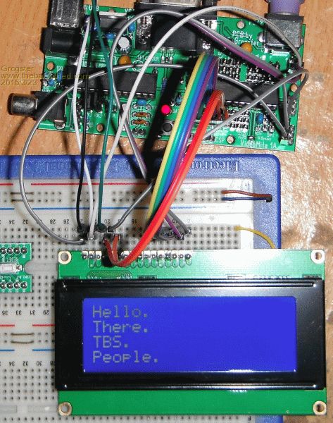
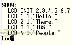
Do you want to send the LCD to me and I could test it here for you, now that I have one setup on my breadboard? EDIT: I note that in your code, you are configuring the I/O pins as DOUT. Comment-out all that code, so you just have the LCD INIT and the LCD commands. The manual says it will configure the pins for you, so perhaps this is somehow causing an obscure bug - I will test that idea now. EDIT: Makes no obvious difference. I would omit them anyway, as the LCD INIT command does all that for you. EDIT: Dug out an old 16x2 display to play with - this one has no LCD backlight. 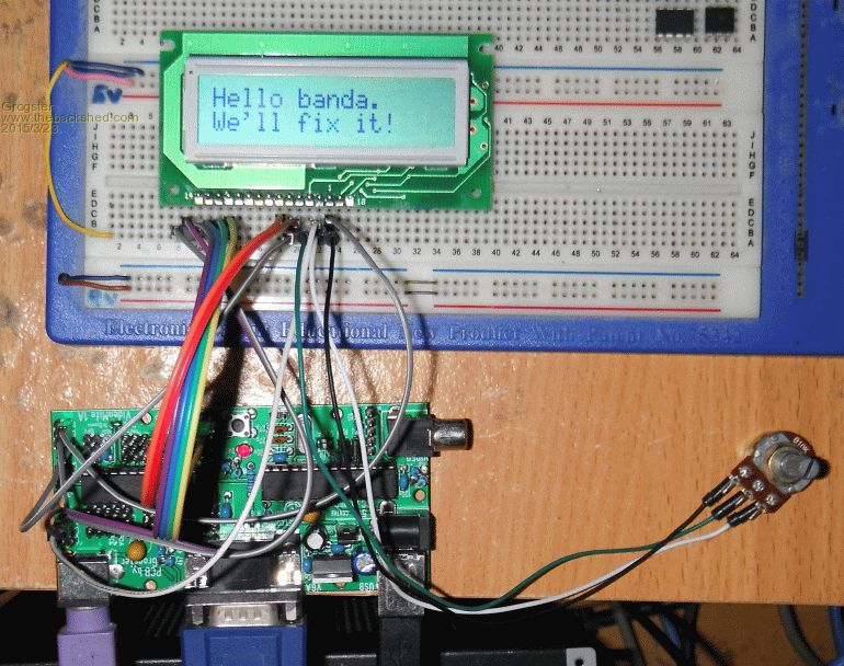
Smoke makes things work. When the smoke gets out, it stops! |
||||
bigmik Guru Joined: 20/06/2011 Location: AustraliaPosts: 2981 |
Hi Banda, I have almost exactly the same module, 1602A V2.0 instead of 1602C.. It looks identical to yours except there are two SMD parts (one populated the other not) just to the left of the row of SMD resistors on the right.. Unfortunately I soldered an I2C adapter to the LCD only yesterday.. But I cranked the contrast to the max and this is the results I get. On Power Up 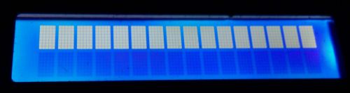
AFTER and INIT 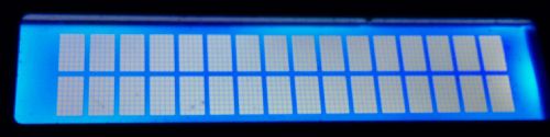
Writing TEXT 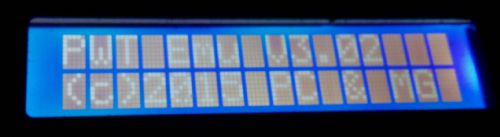
Now, the pictures don't show the difference between the brightness well but the power on is HIGH brightness top line only.. After an init the bottom line and top line are both slightly lower in brightness and are the same intensity... This will prove that the display is initialised OK. In my case I could still see the characters after a write to the LCD but on max contrast this may not be the case with yours.. Of course I adjusted the contrast back to suit my display when running.. Regards, Mick EDIT*** I do have another one of these displays around here somewhere but do you think I can find it? Mik Mick's uMite Stuff can be found >>> HERE (Kindly hosted by Dontronics) <<< |
||||
| Grogster Admin Group Joined: 31/12/2012 Location: New ZealandPosts: 9975 |
An update for you all: 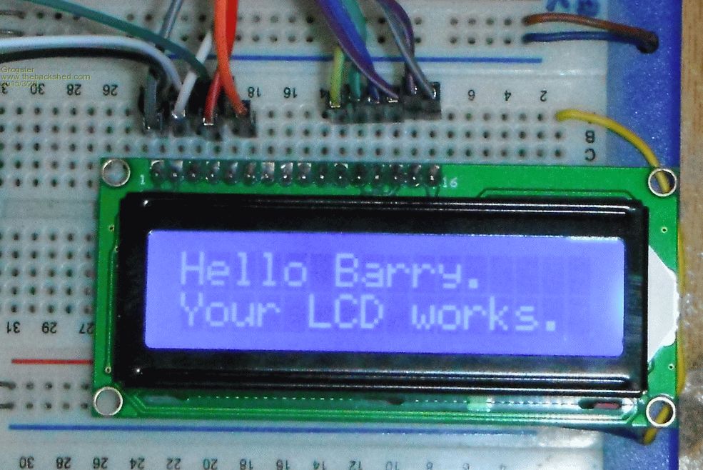
Barry sent me his LCD to test, and as the photo shows...... This is being driven from a 170 chip. My guess at this point, is that the contrast trimmer is not making contact with the breadboard pins - I have seen this before, as trimpot legs are very short, and sometimes they only JUST touch the strips inside the breadboard. In all my tests, I used an external full-size 10k pot with breadboard wires solderered onto it, so I could plug the pot into the breadboard. If I set up the LCD so it is working, then remove the wiper connection to pin3 of the LCD module, the display goes totally blue, with no characters at all, and I think this is what is happening. I will send this display back to Barry, but I would encourage him to use an external pot, or perhaps even the breadboard pot he has, but solder some link wires onto the legs to make them longer, so you can be sure the pot is making contact with the strips in the breadboard.  Smoke makes things work. When the smoke gets out, it stops! |
||||
| WhiteWizzard Guru Joined: 05/04/2013 Location: United KingdomPosts: 2991 |
 Barry's issue almost certainly solved at long last. Barry's issue almost certainly solved at long last.
Thanks for providing 'overseas support' for him once again  |
||||
| Grogster Admin Group Joined: 31/12/2012 Location: New ZealandPosts: 9975 |
Happy to help if I can. Smoke makes things work. When the smoke gets out, it stops! |
||||
| panky Guru Joined: 02/10/2012 Location: AustraliaPosts: 1127 |
banda, Just tested on a 470 with a 4 x 20 blue lcd and works there also. One thing I did note was that with the blue lcd's you have to have the contrast "just right" to see anything and even then it is very faint UNLESS you have the backlight diode in cct. I have a 270 ohm resistor between the anode (A) and 5V and the cathode (K) to ground. Without this, if you wind the contrast up, all you get is the light rectangles with the text not visible. Cheers, panky ... almost all of the Maximites, the MicromMites, the MM Extremes, the ArmMites, the PicoMite and loving it! |
||||
| banda Newbie Joined: 12/05/2014 Location: New ZealandPosts: 35 |
Many thanks to all helpers and advisers. From what I've read such an LCD doesn't seem to be very bright, like me. I think I'm trying to run before I can walk, but now I'm looking at TFTs or OLEDS. I imagine they could be brighter, if dearer, and probably more difficult to run. Banda |
||||
| bigmik Guru Joined: 20/06/2011 Location: AustraliaPosts: 2981 |
Banda, They are not that bad when adjusted well, What value did you use for your Pot? I usually use a 10k. If the contrast pot is turned to either extreme you generally will not see anything legible on the screen. Regards, Mick Mick's uMite Stuff can be found >>> HERE (Kindly hosted by Dontronics) <<< |
||||
| matherp Guru Joined: 11/12/2012 Location: United KingdomPosts: 11498 |
These work great with the micromite as they are 3.3V parts |
||||
| panky Guru Joined: 02/10/2012 Location: AustraliaPosts: 1127 |
Banda, Can you tell me if you are using the backlight diode? When you use that you will find the display is very bright - see my post above. As I said, this also affects how you use the contrast control. Cheers, Doug. ... almost all of the Maximites, the MicromMites, the MM Extremes, the ArmMites, the PicoMite and loving it! |
||||
| banda Newbie Joined: 12/05/2014 Location: New ZealandPosts: 35 |
Praise be! I've got it working! It needed you all to keep me going. It really wasn't worth all the angst. The final success came from Grogster saying the pot thingy I had could have been causing the trouble. It seems he was right. Thanks all again. Banda 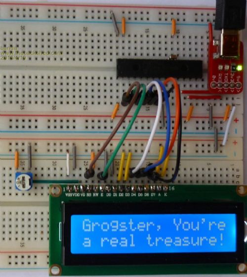
|
||||
| Grogster Admin Group Joined: 31/12/2012 Location: New ZealandPosts: 9975 |
Awwwww shucks.  
Glad to help, and great news that it is going for you now. You live and learn, and one thing I learned a while back was that trimpots often don't make good contact in breadboards - the legs are just fractionally too short. This is why I have and use an external full-size pot with wires on, that I use for any situation needing a trimpot, so that I can be reasonably sure of a good connection. Have fun, and thank you for your perseverance. Many a chap would have given up by now, if they don't have immediate success - I have seen it before, unfortunately, and it can be surprisingly common with newbies to a platform. Please do feel free to post any further questions - the members here are exceedingly helpful and prompt with replies - that's been my experience to any questions I have posted anyway. Smoke makes things work. When the smoke gets out, it stops! |
||||
redrok Senior Member Joined: 15/09/2014 Location: United StatesPosts: 209 |
Here is another LCD source: 20 CHARACTER X 4 LINE LCD W/ LED BACKLIGHT. $4.50us redrok |
||||
| The Back Shed's forum code is written, and hosted, in Australia. | © JAQ Software 2026 |
