
|
|
Forum Index : Microcontroller and PC projects : The TermMite is (re)born . . .
| Author | Message | ||||
| WhiteWizzard Guru Joined: 05/04/2013 Location: United KingdomPosts: 2991 |
Hey Mick, Many thanks for the feedback and kind words. 
The nice thing about this setup is that the TermMite is the main basis for the kids computer into which you can plug in any MicroMite/ArmMite, even one of your MuPs. It does not have to be the (yellow) IO Box with it's increasing range of Modules. This all means that it is actually aimed at 'anyone', i.e. from young to old, and from beginner to expert. The initial 'audience' is primary school kids (aged 7-11) but doesn't mean no-one else can use it. Remember everyone develops at different speeds so this same set of Modules can be used by 'struggling' older people. The training material that is being produced is aimed at 7-11 year olds. Yes they need to be able to type (as they would with other languages) but that is the whole point - it is to teach 'coding concepts' and NOT to control some virtual character that 99.9% of current training 'material' does. I haven't yet mentioned the Robot Arm and the Robot Buggy I have planned. These are simply 'robots' that have MicroMites onboard; and yes you've guessed it, they plug into the TermMite for programming/configuring. Thanks Mick, and good luck in your 'sport' thing - is it over yet? OR is it still to play?? (shows how much I know about sport!) WW I fully take onboard your safety concerns and this has obviously played a major part in the overall design. All six (neodymium) magnets used are located in the I/O Box, i.e. NOT in the Modules. They are 'top-hat' shaped for safety reasons meaning that if they were to 'break free' then they would simply fall into the I/O Box. However they are located between layers of acrylic and a PCB which are self-tapped to each other. As for standing on a module, the plastic will crack but not shatter. For the initial trials we will use the acrylic modules but we want to turn to injection moulding (not sure how the wife will be about one of those at home though  ). But the volume isn't there yet to consider this - but these are the next steps. ). But the volume isn't there yet to consider this - but these are the next steps.
There are no small 'loose' parts in the Modules if they were to break open for any reason (all SMDs are soldered onto a 1.6mm double sided PCB). I am liking the ideas you guys are suggesting for modules - I will just re-iterate that this product could open up lots of opportunities for 'enthusiastic' members here to get involved.
|
||||
| WhiteWizzard Guru Joined: 05/04/2013 Location: United KingdomPosts: 2991 |
The wife is 'understanding' (or at least I think she is!). She even helped me get the big extractor unit out of the van and into the house. Next tool on the list is an injection moulding machine
By the way, several of you asked me to send some pictures of our wedding in Mauritius. For now here is a link to our 'wedding highlights' video . . . . Enjoy! 
WW |
||||
| JohnS Guru Joined: 18/11/2011 Location: United KingdomPosts: 4334 |
A crude oscilloscope - waveforms are captivating - with such as bare wires (OK, contacts not wires) to pick up mains hum from fingers. I think with what you have now it's just some extra software. To debunk the idea that phone masts are dangerous, something to pick up mobile phone signals (and down-scale their frequency!) then show how little is in the air compared to when an actual phone is near a suitable sensor. John |
||||
Grogster Admin Group Joined: 31/12/2012 Location: New ZealandPosts: 9975 |
Very nice video and editing. Looks like it was done professionally. Was that horribly expensive? Stunning opening shot on that video of the two of you standing on the wharf with the sky and the daylight fading - beautiful shot. You look a little like Ralph Finnes - are you sure you are not Voldermort? Smoke makes things work. When the smoke gets out, it stops! |
||||
| WhiteWizzard Guru Joined: 05/04/2013 Location: United KingdomPosts: 2991 |
Morning John, I like the concept. Remember the I/O Box is just a MicroMite, and the Modules are just 'kid friendly' attachments to the MicroMite. With that in mind, do you think you could write some MMBasic software to demonstrate what you are suggesting? I can then get it added onto the rapidly expanding list of Modules. 
WW |
||||
| WhiteWizzard Guru Joined: 05/04/2013 Location: United KingdomPosts: 2991 |
Yes it was a team of three professionals. The video you are watching does not do their work justice as it is low resolution (purely for web viewing). They have taken over 300 photos of which we have picked 70 for our wedding album. Their work is simply stunning and I would strongly recommend them to anyone having a wedding around the Indian Ocean (the area they cover). Lets not talk about cost other than to say please can some of you start placing bulk orders so that I can recover just a small part of the cost How many TermMites do you want to buy Grogs ?
Heres an example of their photographic style: 
WW |
||||
| WhiteWizzard Guru Joined: 05/04/2013 Location: United KingdomPosts: 2991 |
Below is the 3mm laser cut acrylic 'chassis' housed in the screen unit. Most of the holes are for mounting the various PCBs on pillars. 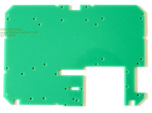
The big cut out is to allow space for the internal 6Ah LiIon battery. The two slots to the left of the battery cutout are for the TFT and OLED ribbon cables. Top cutout is for the Power Switch 'mechanics'; likewise the right hand cutout is for the charging socket/LEDs 'mechanics' First one was cut by hand and took ages! Anyway, now they take about 1minute each piece thanks to the laser 
WW |
||||
| JohnS Guru Joined: 18/11/2011 Location: United KingdomPosts: 4334 |
I was thinking a younger Marcus du Sautoy John |
||||
| Grogster Admin Group Joined: 31/12/2012 Location: New ZealandPosts: 9975 |
I am most certainly interested in your 8" TFT in your plastic case with the 1963 driver, then I can hook it up to some of my MicroMite projects here for testing. I especially like your one, as it is cased up nice and tidy, and means I don't have to worry about casing my TFT up. Are you able to show a photo of the back of this case with the back of the case off with the 1963 interface? IE: Can I get access to the 16-bit parallel interface to the 1963, so that I can build my own little PCB to go inside your TFT case, to drive the screen? Smoke makes things work. When the smoke gets out, it stops! |
||||
| WhiteWizzard Guru Joined: 05/04/2013 Location: United KingdomPosts: 2991 |
Simple answer - no. This is only because I haven't ordered any of these controller boards yet. It was only the other day when matherp mentioned he had the SSD1963 code driving a 7" TFT that I looked to see if my supplier had an 8" SSD1963. They do indeed stock such a screen/controller combination so it seemed logical sense to offer it to you guys. The next time I place a TFT order I will add some controller Boards & 8" TFTs. Regarding making your own PCB for driving the screen via the 16bit interface then this is no problem. In the picture in my previous post (showing the green 'chassis') you can see there are enough mounting holes for affixing PCBs. I may ask you to produce a PCB with the necessary FPC/FCC connector
Once I have received my production PCBs for the kids computer I will take some 'internal' photos and post them here for you to see (I am not prepared to show my prototype boards!) For now I was thinking of offering the following parts to make up a SSD1963 TFT unit: 1> ABS case Choice of black or white. Paint option requires 10+ volume and is a supplier cost option Supplied without any cutouts i.e. no top power button, no charging socket) 2> Front panel 3mm scratch resistant acrylic with only the 8" 'window' i.e. no OLED window. Can choose paint colour (white is shown above) 3> Rear Panel. 3mm scratch resistant acrylic. Can choose paint colour (but white looks best). Suggest no logo as this is easier to produce as it only requires one spray paint process. NOTE: Customised holes can be cut in this for any external connectivity. The rear panel is 148mm x 148mm 4> Inner chassis 3mm acrylic for fixing any internal PCBs to. This would be a variant of the green piece as shown in my earlier post. Colour can be chosen but green or clear are the cheapest. 5> Spacer 6mm acrylic for holding the 8" TFT in the exact place for perfect alignment 6> Foot plate 5mm white acrylic but other colour options available. Three recessed anti-slip feet (black). If requirements are for wall mounted then I do have kits for this BUT then we need to reconsider external connection 'entry points' 7> 8" TFT 800x480 + SSD1963 controller Basically I can customise things but rather than get bogged down with lots of different things then I think the white option (as I have used above) looks the nicest. I haven't created one of these yet for the SSD1963 so I would want to assemble one first before offering it to everyone. If you want to be the person to allow me to test this then drop me a PM
Let me know your thoughts . . . WW |
||||
kiiid Guru Joined: 11/05/2013 Location: United KingdomPosts: 671 |
Phil, this is excellent and very eye-catching! I love how it looks. Only one question from me, maybe I have missed it, but it looks like there is no external storage available. How are the kids supposed to 'exchange' programs? Actually, I've got a few more questions. Are you going to sell these or they will be only available through some school scheme? I might be seriously interested in getting one or two of these when they become more available, to test with my kids. Did you manage to keep the end-user price (whoever that will be - people or schools), low enough to be attractive? http://rittle.org -------------- |
||||
| WhiteWizzard Guru Joined: 05/04/2013 Location: United KingdomPosts: 2991 |
Thanks Kon. The customer specifically requested no external storage (on the basis that SD cards get lost, kids take them out, someone has to manage them, etc, etc). A current issue with Raspberry Pi's is that the teacher can spend a long time getting the kids & Pis started due to issue with 'missing' SD cards. This is fine for the initial target audience where the concepts of coding are taught using very short programs. However, that said (and as hinted in an earlier post) I am working on an external SD card (lower left edge of screen unit). This will open things up to a much larger market. If there is enough interest then these will be readily available (I am setting up a new company for all of this). I will certainly be offering the TermMite (Screen & keyboard) as a product on MicroMite.org as soon as funds permit me to buy stock. Perhaps I should take back orders to raise funding?? The school computer is not intended to be a �25 computer like the Pi. It is aimed as a professional educational piece of kit that 'actually' works in a classroom environment. I have seen some real 'cr&p' out there that costs way over what you would expect to pay. Feedback from educational establishments has been very positive so I have aimed the cost identical to low-end laptops. The profit margin is lower than hoped so now I will be relying on volume to regain the investment put in. PM me if you are serious about getting one from me - like I say, if several people 'backorder' then I can move forward quicker in getting some out with you guys. WW |
||||
| Grogster Admin Group Joined: 31/12/2012 Location: New ZealandPosts: 9975 |
Hey Phill - does your 8" screen have touch? Perhaps a touch membrane that you are not actually using, but if it is there, I could use it. ...or is the LCD just an LCD? Smoke makes things work. When the smoke gets out, it stops! |
||||
| WhiteWizzard Guru Joined: 05/04/2013 Location: United KingdomPosts: 2991 |
G, The particular screen that I am using does not come with the touch option installed BUT it is an available option to add it (resistive). I do NOT intend using touch for the kids computer. The enclosure I am offering to TBS members would need modifying if you wanted to incorporate touch. Note that if touch is used then the current stand/foot on the screen unit will not be sturdy enough. I was involved in designing touch screen solutions back in the mid 90's for retailers here in the UK. Back then the monitors were CRTs which had enough 'mass' to support being touched. But when the suppliers then started adding touch to LCD screens they didn't understand why I kept saying they need to redesign their stands to allow the LCD monitor to be 'touch friendly'. So yes, I can cut out a 'touch window' in the front panel, but the foot design would ideally need modifying. WW |
||||
| paceman Guru Joined: 07/10/2011 Location: AustraliaPosts: 1329 |
Phil, I haven't noticed anyone mention a sound module. DX.com supplies those Catalex modules using the YX5300 chip for $6.50 and it includes a micro SD card. They read MP3 and WAV format and sound pretty good through computer speakers. I guess you could use a small speaker or piezo even in your module. Another possibility could be an IR receiver module &/or transmitter to control something (MP3's as above maybe). Those small IR remotes are very cheap and could be used with that. Also a DHT22 temp/RH module maybe - turn ON/OFF a little fan maybe? Greg |
||||
| Grogster Admin Group Joined: 31/12/2012 Location: New ZealandPosts: 9975 |
Hey Phill. 
Not worried about the screen falling over when touched - I would be mounting them on the wall as mimic panels, so they could not move. Smoke makes things work. When the smoke gets out, it stops! |
||||
| plasma Guru Joined: 08/04/2012 Location: GermanyPosts: 437 |
Like the idea and the design . Are this printed parts ? |
||||
| WhiteWizzard Guru Joined: 05/04/2013 Location: United KingdomPosts: 2991 |
@plasma No - not 3D printed (quality was too poor!). Opted to use a CO2 laser to cut all the parts out of acrylic sheets. WW |
||||
| Octatron Newbie Joined: 01/04/2015 Location: United KingdomPosts: 27 |
Phil Excellent idea, case is well thought out. I did a stint of teaching engineering a few years ago and one of things I found was that equipment needed to be quick to set up and easily understood.... by the teacher. Your Termite meets this requirement. I'm interested about the keyboard you used and the mods you made, perhaps you could post some details. |
||||
| WhiteWizzard Guru Joined: 05/04/2013 Location: United KingdomPosts: 2991 |
Thanks Roy for your comments. I see from your profile that you are in the UK. I would like a quick chat if possible regarding your 'teaching days' - I can then tell you more about the keyboard!! If you're ok with this then please PM me your contact details (or email them to me to save filling up my TBS inbox
Thanks, WW |
||||
| The Back Shed's forum code is written, and hosted, in Australia. | © JAQ Software 2026 |
