
|
|
Forum Index : Microcontroller and PC projects : MicroMite+ Explore64 PCB 1C...
| Author | Message | ||||
Grogster Admin Group Joined: 31/12/2012 Location: New ZealandPosts: 9975 |
@ Jim - Supervisory chip has no cap on the MCLR line, so you can program the 470 fine with it in place. The Skinnymite has one of those 130's, and I was able to program it just fine. @ TZA - Like this?: 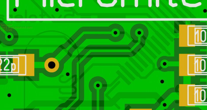
Smoke makes things work. When the smoke gets out, it stops! |
||||
| MicroBlocks Guru Joined: 12/05/2012 Location: ThailandPosts: 2209 |
Yes. It is one of the last steps i always do when adding a copper pour. Often moving a few vias can make a big difference. Microblocks. Build with logic. |
||||
| MicroBlocks Guru Joined: 12/05/2012 Location: ThailandPosts: 2209 |
I see that you have a PTC after the diode and before the voltage regulator. This is not necessary as the voltage regulator has its own overcurrent, overtemperature and short cicuit protection build in. It might be better to put that PTC right after the USB and before the diode. In that case it will protect the USB supplied power. In most cases a USB already has protection built in anyway so you could even drop the ptc. Also make sure you get the 1703A version as it is the new and improved one recommended for new products. As an aside. Did you ever tested a PTC? Especially the small SMD ones get rather hot and i even had some that reflowed themselves again. The one with leads at least has air flow. For me that worked better. Also a PTC will increase its resistance after it has become actieve, and it can take hours to weeks before it is in a good state again. All depending on the hold and trip values the PTC has of course. I wish the USB specs would have the power supply as 6V or even 12v, then we could just put a regulator behind it and done. Also could you inform we what via/trace and space sizes you are using. I am about to prepare some to send to the same pcb manufacturer and on their site it is not that clear. Microblocks. Build with logic. |
||||
| Grogster Admin Group Joined: 31/12/2012 Location: New ZealandPosts: 9975 |
Hi TZA. 
Re. PTC - Yeah, you make good points on all fronts there. I think I will just drop it. There is an area around the PTC, so that if/when it trips, it can properly heat up without the copper pour sucking away its heat. Having said that, yeah, I think we can drop the PTC, actually. What are other members' opinions of that and the reasons behind? On the specs, they have tab on the page - scroll down a little, and click on the "PCB Capabilities" tab - all their specs are listed there. As to what I use, I am using 0.2mm tracks, 0.4mm ground-plane spacing, and the vias are 0.7mm OD, 0.3mm ID. 0.3mm is the minimum drill size for SH2U. The fatter tracks are 0.6mm except for the one feeding the ICSP and SD card socket, which are 0.5mm Smoke makes things work. When the smoke gets out, it stops! |
||||
| atmega8 Guru Joined: 19/11/2013 Location: GermanyPosts: 738 |
Hi Grogster, here in Germany it is nearly not possible to get the Format of the Reset Switch you use (When ordering by the standard Distribution which hobbyist use).... Standard Switches have a quadratic footprint like this one: Switch Any chance to change it? Atmega8 |
||||
| WhiteWizzard Guru Joined: 05/04/2013 Location: United KingdomPosts: 2991 |
@atmega8 Can you order from Farnell / Element14? If so then part no. 1629616 BUT they want US delivery charge 
Anyway, that said, if you need one or two then I can send you  |
||||
| atmega8 Guru Joined: 19/11/2013 Location: GermanyPosts: 738 |
@WW, Farnell and Element14 are not for Hobby... In Germany, Reichelt, Pollin, Conrad are very popular, but they all sell the quadratic Version. Think you for your offer to send some switches over the channel. I will try to solder a jumper instead of this switch. |
||||
| WhiteWizzard Guru Joined: 05/04/2013 Location: United KingdomPosts: 2991 |
I have to ask: what do you mean by 'not for hobbyists'? I don't know if it is different there in Germany, but here in UK I can order a single resistor from either RS or Farnell up until 8pm and have it delivered free of charge to my home the next day. You do not have to buy a 'large quantity' of items, and their prices are very low. Sure they don't sell 'redundant' boards where you may find lots of 'useful' components that you can re-use; perhaps this is what you mean? And neither do they have a shop you can pop into to browse. When I was very young I use to love popping to the local electronics shop where I could buy many populated PCBs full of all kind of goodies. I was in the same town that all the Marconi factories were based so lots of great things were obtained! However, these shops have all disappeared now (the last one was Tandy/Radio Shack); much like Marconi's has disappeared too. Slight correction to this; Maplins is a 'booming' high-street electronics outlet but most useful stuff is web-order only (and their prices are very high due to their running costs). So I am curious; what do you mean by 'not for hobbyists' . . . WW |
||||
bigmik Guru Joined: 20/06/2011 Location: AustraliaPosts: 2981 |
Hi Atmega, Just buy them off eBay 100pcs for about $3US Regards, Mick Mick's uMite Stuff can be found >>> HERE (Kindly hosted by Dontronics) <<< |
||||
| Grogster Admin Group Joined: 31/12/2012 Location: New ZealandPosts: 9975 |
Totally agree with BigMik here - that is the way to do it, and you will never run out of that switch again.
The Element14 part number is listed, as this SHOULD remain constant, being that it is from a reputable supplier, which is what it needs to be for article printing purposes. Smoke makes things work. When the smoke gets out, it stops! |
||||
| atmega8 Guru Joined: 19/11/2013 Location: GermanyPosts: 738 |
Thank you, The ebay offer delivers not to Germany. RS/Farnell take appro. 6� freightcosts, free when you order for more than 55�. Thats all ok. THX |
||||
| Grogster Admin Group Joined: 31/12/2012 Location: New ZealandPosts: 9975 |
As with WW's offer, I would be happy to send you some free buttons if you like - I have several hundred, so I could send you some, you just pay postage, which is standard letter-rate: US$2.50 airmail - PM me if you are interested. Smoke makes things work. When the smoke gets out, it stops! |
||||
| bigmik Guru Joined: 20/06/2011 Location: AustraliaPosts: 2981 |
Hi AtMega A further search on eBay (German eBay) shows more sellers Here You just need to find the seller that ships to you at a price you are happy to pay Regards, Mick Mick's uMite Stuff can be found >>> HERE (Kindly hosted by Dontronics) <<< |
||||
| atmega8 Guru Joined: 19/11/2013 Location: GermanyPosts: 738 |
switches Ordered this from UK. THX |
||||
| Geoffg Guru Joined: 06/06/2011 Location: AustraliaPosts: 3362 |
Regarding the discussion regarding using a jumper instead of a diode to isolate the USB +5V. It has just occurred to me that a jumper would be much better than a diode. This is because when I implement the USB keyboard feature the USB socket will be required to supply power to the keyboard and a diode will prevent this. Sorry Grogs, I know that I suggested the diode in the first place. I have on order a couple of Mini USB Male to Type A Female Jack cables. I am hoping that these will enable a USB keyboard to be plugged into the Explore64's USB socket so that users can swap between USB console or keyboard functionality at will. BTW I have not actually started on the USB keyboard implementation so at this stage I cannot guarantee how/if it will work. Geoff Geoff Graham - http://geoffg.net |
||||
| robert.rozee Guru Joined: 31/12/2012 Location: New ZealandPosts: 2528 |
this just jogged my memory - is the pin between D+ and GND on the USB connector not used to sense an OTG (on-the-go, reversed master/slave) cable: 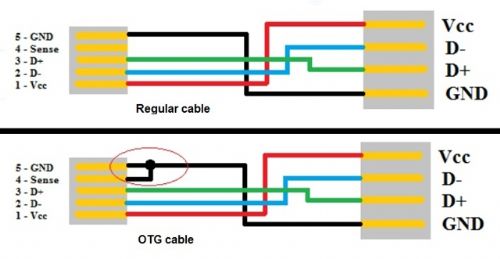
(from: http://tech.firstpost.com/news-analysis/how-to-make-your-own-usb-otg-cable-for-an-android-smartphone-29503.html you might wish to route this sense pin to an input pin on the MX470, and use that to sense when an external USB keyboard is plugged in. at the same time you could replace the diode with a MOSFET (with internal bypass diode) that when turned on would route power out the USB port. all this would consume 2 i/o pins on the MX470. cheers, rob :-) |
||||
| Grogster Admin Group Joined: 31/12/2012 Location: New ZealandPosts: 9975 |
It's cool. 
Are you happy enough with the "External" jumper as the board is arranged now, or were you thinking of something else? If you are happy(and no-one else has any issues), then I can remove the diode totally, and upload some new images. EDIT: @ Rob - to do the MOSFET thing, as we have a common ground, it would have to be a P-channel MOSFET, yes? A high-side switch on the positive to the USB socket. And if that is the case, we'd also need the NPN transistor to pull the gate low enough like in the other thread when we talked about this, yes? I could fit a couple of SOT23 footprints in there easy enough, once the diode footprints are done away with...... Smoke makes things work. When the smoke gets out, it stops! |
||||
| robert.rozee Guru Joined: 31/12/2012 Location: New ZealandPosts: 2528 |
further reflection. the MOSFET should be wired up like this: 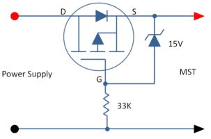
(from: http://www.ozqrp.com/rev_pol.html ) the zener diode and 33k resistor are not necessary, D goes to USB socket V+, S goes to 3v3 regulator input, G goes to the USB sense pin directly. there should be a 10k or so pullup from G to S. when power is fed into the USB socket (from a host PC), the diode in the MOSFET will conduct. but the MOSFET will not switch on, as the gate is pulled high by the 10k. when the 'sense' pin is tied low by the OTG cable, the MOSFET will conduct, allowing power to flow in the reverse direction, from E64 board back into the attached keyboard. retaining the existing (external) diode may be desirable, as it my have a lower forward voltage drop than the one in the MOSFET. cheers, rob :-) |
||||
| robert.rozee Guru Joined: 31/12/2012 Location: New ZealandPosts: 2528 |
yes - a P-channel MOSFET. because it would be a rather small device and low currents are involved, the -5v gate voltage should suffice. |
||||
| Geoffg Guru Joined: 06/06/2011 Location: AustraliaPosts: 3362 |
I have read this thread a few times and I am still a little confused. I presume that the pin labelled Vbus on your latest board is the +5V from the USB socket. I personally would have thought that a two pin jumper that Jim had in this illustration was better: 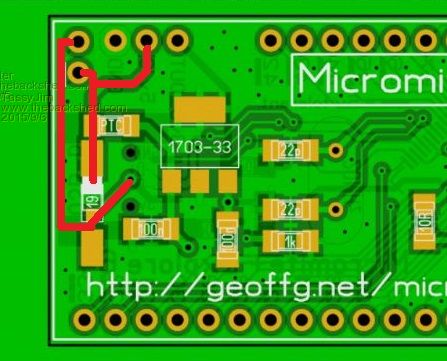
That way most constructors would solder both header pins to the top of the PCB and then simply slide on or off a standard 0.1* shorting jumper as required. With the latest version of your PCB the connection must be made externally which would be a pain, especially if the PCB was floating free (not plugged into a breadboard). With Jim's method you could also not install the inboard pin of the jumper pair and then have the same effect as your current board. As I said, this thread has me slightly confused so I might be barking up the wrong tree. Regarding Rob's MOSFET idea: Great idea but I still think that a jumper is best - it is simple, has zero voltage drop and leaves the user in full control. I am hoping to use Grog's board as the basis for a Silicon Chip article introducing the MM+ so this is why simplicity and easy to find parts are important. Geoff Geoff Graham - http://geoffg.net |
||||
| The Back Shed's forum code is written, and hosted, in Australia. | © JAQ Software 2026 |
