
|
|
Forum Index : Microcontroller and PC projects : MicroMite controlled 4-CH stereo...
| Author | Message | ||||
| akashh Senior Member Joined: 19/01/2014 Location: IndiaPosts: 115 |
Great project! Just a quick question slightly off topic - what software do you use to design the PCB? I like the transparency effects, it looks very professional. Akash |
||||
Grogster Admin Group Joined: 31/12/2012 Location: New ZealandPosts: 9973 |
Sprint Layout 6 Smoke makes things work. When the smoke gets out, it stops! |
||||
| Grogster Admin Group Joined: 31/12/2012 Location: New ZealandPosts: 9973 |
UPDATE New version of the main pre-amp board. This is a 100x100 panel, but with two seperate boards on it - the main board, and the input sockets board. Technically, this is a multi-design panel, and the likes of Shenzhen2U will charge an extra US$9 for designing like this(they call it 'Sub-boards'), but I still think it is cheap for the price - US$20 or so for ten sets of boards - pretty good! 
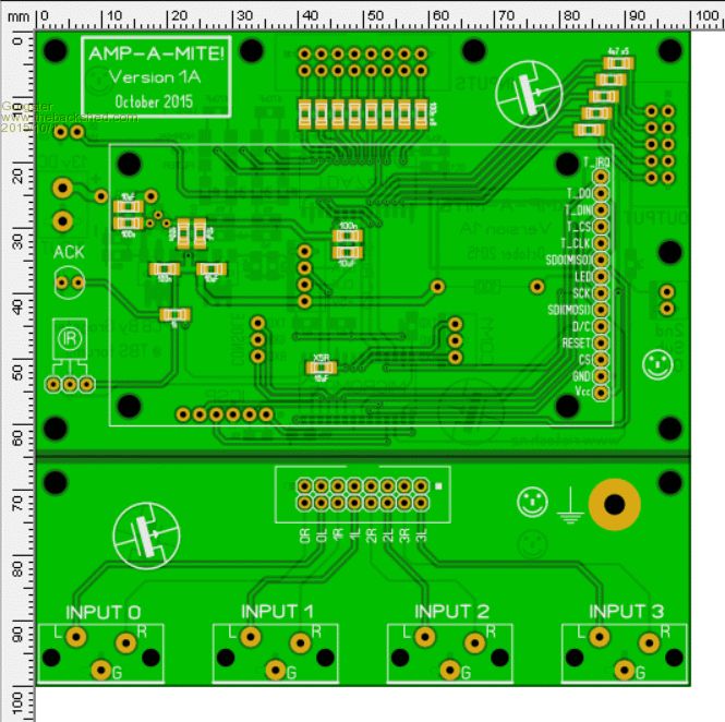
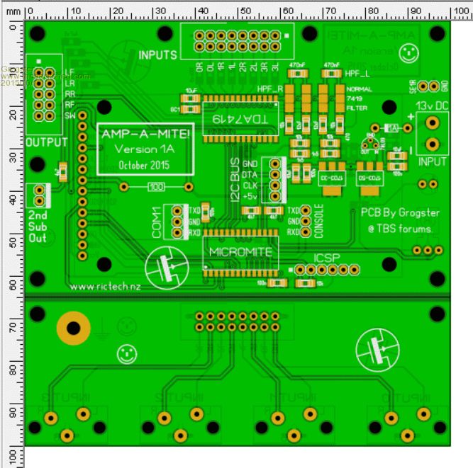
I plan to order all these boards next week after a few more tweaks, and while I wait for the boards to arrive, I can concentrate on doing the case. Jaycar sell a lovely case for this kind of project, and not to bad on cost: HB5556 - which is probably the one I will elect to use. If that one proves to be too hard to fit everything in, then I will look at getting a custom laser-cut and powder-coated case made - they are not really that expensive. EDIT: On the HDMI side of things, eBay has come up trumps again, with an HDMI audio extractor for NZ$18(about US$11.60) - Link. This will only be plain stereo me thinks, but it is probably of better quality then the analog out of the Raspberry-Pi I am using at the moment. The Pi's analog audio out is not really any good for amplification(drenched in white and decoder noise), but I guess it would be OK for use on an old TV set - what it was designed for, I guess. EDIT: This is the remote control I am going to use - hopefully. 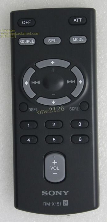
It is simple and not covered in buttons, but should allow all the basic features to be included. Being a Sony remote, this one is most likely a 40kHz one, but element-14 sell Vishay TSOP4840's for only a couple of bucks or so, so that will be the receiver to go for. I will try it with my 4838's for a start, but the 3840 would be desirable. These remotes are easy to find on eBay for about US$4 or so, or brand-new ones can be had from a few traders for only US$10 or so, but the shipping cost from America is what keeps me buying from China most of the time as far as eBay is concerned.... Smoke makes things work. When the smoke gets out, it stops! |
||||
| matherp Guru Joined: 11/12/2012 Location: United KingdomPosts: 11424 |
Talking about amplifiers and pre-amps..... Ages ago I built a stereo pre-amp based on the PGA2310 stereo audio volume control chip. This used an IR control and also control by a rotary encoder. It used two Picaxe chips, one 8-pin for the IR and the other 28-pin to do all the rest. IR is blocking on the Picaxe. The display is a standard 16x2 LCD. The board supports 4 channels switched via relays with one available internally to connect to a DAC if built into an amplifier. Connection of the audio signals is by PCB mounted dual phono connectors Supply requirements are one or more transformers to provide 9-0-9 and 0-6 outputs The circuit is attached: 2015-10-01_104930_Preamp_-_Project.pdf and the layout was carefully done to separate the digital and analogue circuits with a single point ground connection 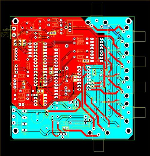
I've got a number of these boards left. If anyone wants one send me a PM. It should be possible to use a 28-pin Micromite to replace both Picaxe with a bit of patch wiring. Alternatively I can make the Picaxe code available if required. |
||||
| Grogster Admin Group Joined: 31/12/2012 Location: New ZealandPosts: 9973 |
I like the darlington-driver IC idea - had not thought of that, and now that I have added a 6th relay for amplifier power switching, I think I will replace all those 337 drivers with one simple IC. Nice one.  Smoke makes things work. When the smoke gets out, it stops! |
||||
| Grogster Admin Group Joined: 31/12/2012 Location: New ZealandPosts: 9973 |
UPDATE Thanks to matherp, I have replaced all the 337 relay driver circuits with a single SOIC ULN4003A darlington driver IC, and this has allowed me to shrink this board by 15mm on one side - yay! 
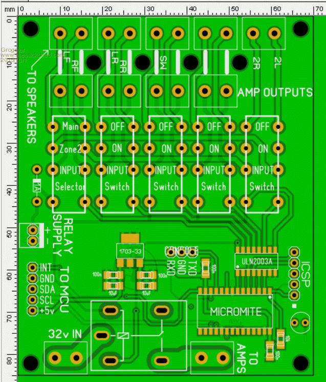
I have added a grunty 10A relay to switch the main juice on and off to the amp modules when the system is "Off" in standby. I have also added a couple of bits to the main preamp board to turn off the LCD backlight when in standby. There is also a line going back to the preamp board called INT. This is an interrupt line from the relay board back to the preamp board, so that if it wants the attention of the master, this can be used to tell the master that the relay slave wants to talk to it. I plan to add some extra temp sensors etc to the amps and maybe PSU, which the slave board(the relay one) can monitor, and if it detects anything urgent, it can signal the master that it wants to send some info, and if this data is bad enough - like overheating - the system can shut itself off and display a message to that effect on the LCD. 3:37AM now, so enough for tonight!!!!!  
EDIT: There are still a couple of errors on this board - will fix them tomorrow. 32v amp switching relay coil is not connected, and the CONSOLE word is on top of the pins at the moment. 2003 main GND needs to be thicker. No series resistors needed anymore(the 1k network in previous images), as the 2003 has 2k7 base resistors built in - this is really neat. More tweaking tomorrow. Smoke makes things work. When the smoke gets out, it stops! |
||||
| WhiteWizzard Guru Joined: 05/04/2013 Location: United KingdomPosts: 2977 |
Grogs, What size TFT are you using there? I have read and re-read the posts but can't find mention of it anywhere!! 
From the dimension of the PCB I assume it is a 2.4"? Thanks for 'educating' me . . . WW |
||||
| Grogster Admin Group Joined: 31/12/2012 Location: New ZealandPosts: 9973 |
Yes, 2.4" SPI 240 x 320 with touch controller. ...pretty common on eBay for about ten bucks... Graeme sleep now....... Smoke makes things work. When the smoke gets out, it stops! |
||||
| Grogster Admin Group Joined: 31/12/2012 Location: New ZealandPosts: 9973 |
UPDATE OK, I have finished the relay board: 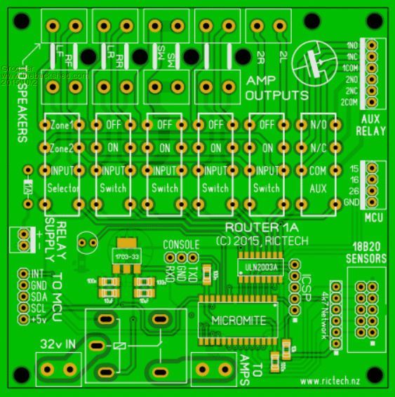
I added one more relay so as to use the full ability of the ULN2003 chip. This last 7th relay is not assigned to anything, but it might come in useful at some point. The remaining three unused pins are routed to the MCU header - they might be useful later too - you never know. The plan is to control the relays with a single byte from the master. The byte will control the PORT command for the relays connected via the 2003 to pins 2-7 by setting the PORT command. PORT(2,7)=BYTE_SENT_FROM_MASTER kind of thing. The board allows for up to five separate 18B20 temperature sensors running with parasitic power, to monitor up to five different heat-spots inside the amp. Naturally, you don't need to use these unless you want to - my initial code won't even allow for them - this is future-planning. 
Traces made much thicker around the subwoofer speaker relay, as this one when thumping hard, can be passing a quite respectable current. Trace width of 2.5mm on 1oz copper board allows for up to 5 amps of thumping current for the sub - about 160W RMS for the sub(at 32v) The other speaker tracks are 1mm, which is good for 2.5 amps on 1oz copper - about 80W RMS per channel(at 32v). What all this means is that unless you are running the amp at the Motorhead #11 setting(out of ten!), then the relays and tracking around them should be able to cope with just about any amps you connect to the system. I will be ordering the boards next week, so I can start building. I expect that the problems will surface once I start trying to talk to the 7419 chip via I2C.
But you never know - things might just work - that would be nice. Smoke makes things work. When the smoke gets out, it stops! |
||||
| WhiteWizzard Guru Joined: 05/04/2013 Location: United KingdomPosts: 2977 |
Looking good - hopefully 'sound' good too |
||||
| viscomjim Guru Joined: 08/01/2014 Location: United StatesPosts: 925 |
Thats a great looking board. Can't wait to see how you get along with the I2C commands and the display layout. Keep it up.... |
||||
| viscomjim Guru Joined: 08/01/2014 Location: United StatesPosts: 925 |
Grogster, do you have any concerns with driving the uln2003a with 3.3v? I am trying to find information on doing this as the chip is speced at 5v. I'll keep searching.... EDIT... Just found this... Note: Although this is specified as a 5V chip, it works fine at 3.3V although max output current will be reduced to at max 300mA |
||||
| Grogster Admin Group Joined: 31/12/2012 Location: New ZealandPosts: 9973 |
...as you say. As the DIL relays use about 30mA, and the larger SPDT one for switching the amp power uses about 40mA or so, this should not prove to be a problem - hopefully! Smoke makes things work. When the smoke gets out, it stops! |
||||
| Grogster Admin Group Joined: 31/12/2012 Location: New ZealandPosts: 9973 |
UPDATE While I wait for the PCB's to arrive, I have been using Screamer Radio to stream radio from the net for background music, but I miss my favourite station, so I have found a cute wee FM radio module controlled by I2C, which I will add to this project. Technically, this means I will lose input zero, as I will dedicate that to the radio module, assuming I can get it working OK. Stereo FM radio I2C module for US$5 It would seem they use one 3.5mm socket as an aerial, and the other is audio out. It looks like they are using a little SOIC-8 op-amp as a pre-amp, going by the image. As I am already using the I2C bus for the relay board, I can plop this in parallel. Being controlled by I2C, this means I can use the LCD to show the radio settings.
The only thing that I am lost with at the moment on this module, is how you go about telling it what frequency you want it to look at. This is specified as 13 bits in data bytes 1 and 2, but there is no chart in the datasheet telling you what the truth table is for all the frequencies, which has me stumped at the moment. For example: how would you tell it you wanted to look at 100.8FM kind of thing? If anyone knows how this is likely to be done, please do let me know. I2C commands are covered in charts from page 10 of the PDF for the TEA5767, and the PLL stepping is covered from page 14. The research continues.... EDIT: The formula for calculating the 14-bit frequency word is hiding at the bottom of page 30 - quite a ways from page 14! Smoke makes things work. When the smoke gets out, it stops! |
||||
| WhiteWizzard Guru Joined: 05/04/2013 Location: United KingdomPosts: 2977 |
Take a look at this Application Note. Goto Page 21 (section 4.2)
Good luck . . . |
||||
| viscomjim Guru Joined: 08/01/2014 Location: United StatesPosts: 925 |
Hi Grogster, have you had a look at the RDA5807 FM STEREO module. I think it is compatible. Also, HERE is a link to a driver used with Great Cow Basic to run the little fm radio module. You might be able to pull some info from that. Good luck with this. I would really like to see this working. EDIT... GCB does I2C a bit different as far as the units address. I think they don't include the extra bit so the address is in half of what we would do with the uMite. EDIT... Some more info HERE I think. |
||||
| Grogster Admin Group Joined: 31/12/2012 Location: New ZealandPosts: 9973 |
Me too.
I will post a link to a video, if I get things working well enough. Had not heard of the other radio module, so will check that out also. Smoke makes things work. When the smoke gets out, it stops! |
||||
jman Guru Joined: 12/06/2011 Location: New ZealandPosts: 711 |
Hi G Here's one I did a while back http://www.thebackshed.com/forum/forum_posts.asp?TID=4896&KW=Radio Still use it Regards Jman |
||||
| Grogster Admin Group Joined: 31/12/2012 Location: New ZealandPosts: 9973 |
Excellent - cheers - will look at that code, as it will help me in the I2C side of things. Not sure if my modules use the same protocol, but I seem to remember doing a comparison, and they were both the same as far as the I2C instructions were concerned.(might be wrong there) Smoke makes things work. When the smoke gets out, it stops! |
||||
| Grogster Admin Group Joined: 31/12/2012 Location: New ZealandPosts: 9973 |
UPDATE My dinky Sony remotes arrived today, so I immediately hooked up a TSOP4840 to a MM, and ran the test code to find the codes. I post this chart here, for anyone else to use, should they wish to use this remote. 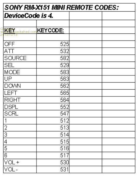
Smoke makes things work. When the smoke gets out, it stops! |
||||
| The Back Shed's forum code is written, and hosted, in Australia. | © JAQ Software 2026 |
