
|
|
Forum Index : Windmills : combined Wind Power and Solar Power
| Author | Message | ||||
ericvr Newbie Joined: 24/11/2007 Location: AustraliaPosts: 37 |
I whole heartedly concur with this. You should NEVER look directly at high intensity LED's or laser torches!!!!!!! Ericvr limited greenie |
||||
| dwyer Guru Joined: 19/09/2005 Location: AustraliaPosts: 575 |
Hi everyone That is true Ericr One night i was ready books during at night time at the time l was in bed after reading books with high intensity LED lamp over my head for fews hours next morning l suffer some things sticking like glue on my both eyes plus bit burring and l relizise that comming from LED No wonder anyone or Heath Dept aware about this problem ? 
IAN |
||||
Bryan1 Guru Joined: 22/02/2006 Location: AustraliaPosts: 2174 |
come on guys I only mentioned the led's in part of my reply to Eric. Now we've hijacked the top thread Eric started. If any futher discussion is on led's lets just make another post. Now if everyone is in agreement lets let Glenn delete all the hijacking posts to retore the integrity of Eric's top thread. |
||||
| Gizmo Admin Group Joined: 05/06/2004 Location: AustraliaPosts: 5187 |
Thats all right Bryan, its only a little off topic and Eric was interrested too, so I'll leave it as is. Glenn The best time to plant a tree was twenty years ago, the second best time is right now. JAQ |
||||
| ericvr Newbie Joined: 24/11/2007 Location: AustraliaPosts: 37 |
Here are some more pictures of the equipment that I used: 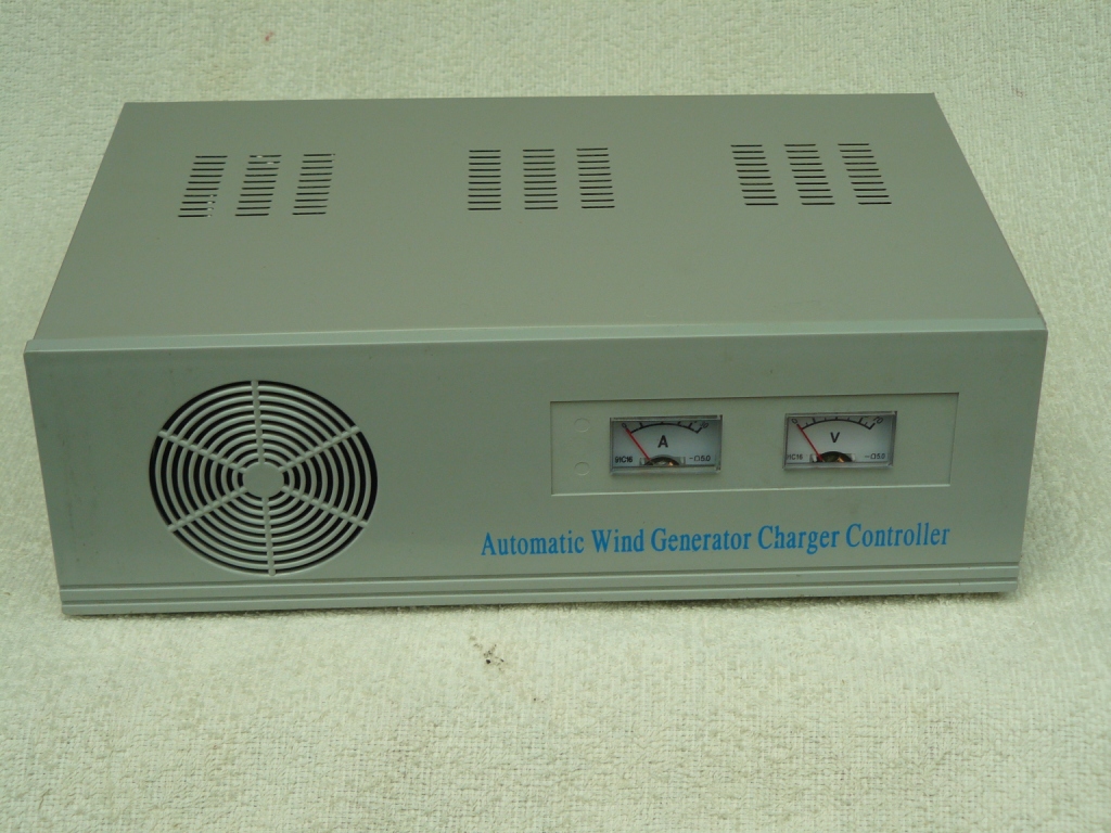
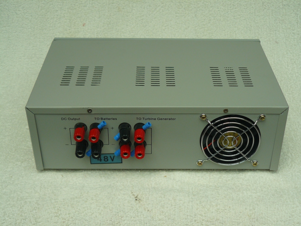
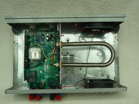
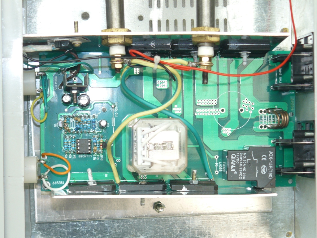
These pictures are of the control unit that came with the 1000 watt 48 Volt wind generator from A+ Imports. As you can see it is a shunt type regulator as shown by the "U" shaped heating element on the right hand side in between the two fans, of which I hope, one sucks and one blows. The last photo is of the circuit board. The cable that we are using is 1.5 mm diameter conductors which should be enough to carry the current of each phase, without too much voltage drop. has anyone measured the current of each phase of a three phase generator? I worked it out at about 7 amps per phase for 1 KW at 48 volt. because the total current for 1 KW @ 48 volts is approximately 21 Amp. Ericvr limited greenie |
||||
| GWatPE Senior Member Joined: 01/09/2006 Location: AustraliaPosts: 2127 |
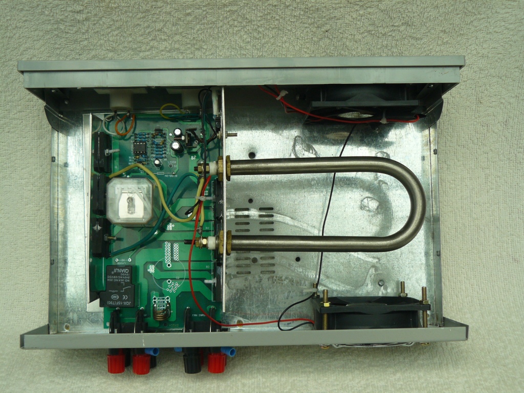
Hi ericvr, is the unit above unmodified? I notice the components in the closeup at the bottom of the last photo. Someone must have been in a hurry on the assembly line. These components are mounted on a heatsink, presumably for a reason. I notice the gaps between the components and the heatsink. Maybe the manufacturer has built in a place for the equipment to fail. I cannot think of any reason the components would not be firmly bolted to the heatsink. You have removed the cover so warranty may be void. I would fix the problem before commissioning. cheers, Gordon. become more energy aware |
||||
| ericvr Newbie Joined: 24/11/2007 Location: AustraliaPosts: 37 |
Hi Gordon, Do you mean the gap between the semiconductors and the heatsink? I have looked at the mounting of the devices and they are tight I think that it is a moulding imperfection on the devices. On closer inspection, with a magnifier it looks as if the heatsinks are in close contact with the heatsink.and the screws are very tight. So I am confident that it will be OK. And yes the unit is in its original state no modifications at all. Do you know of any mods that can be done to increase the performance? Thanks for alerting me to that Eric limited greenie |
||||
Highlander Senior Member Joined: 03/10/2006 Location: AustraliaPosts: 266 |
Hi Eric, yeah those controllers have a bad name. A real pity, as the mill's seem to be pretty good. I think when the Chinese have a Q/A system widespread our manufacturing sector will demise. 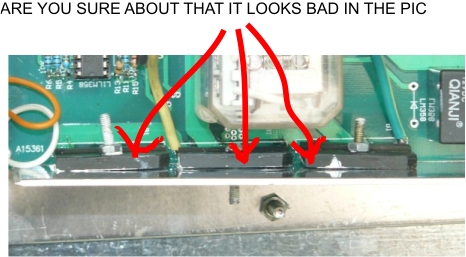
Central Victorian highlands |
||||
| ericvr Newbie Joined: 24/11/2007 Location: AustraliaPosts: 37 |
Yes, I have had a good close look at it and the screws are very tight and with a magnifier (3x) I can see that the metal part of the semiconductor is in close contact with the heatsink, I was also toying with the idea of putting the devices on a proper heatsink, instead of just the piece of aluminium. I can buy a heatsink that will fit in the case from Jaycar or Dick Smith. But I do not know how hot the devices get. Ericvr limited greenie |
||||
| dwyer Guru Joined: 19/09/2005 Location: AustraliaPosts: 575 |
Hi Ericvr I am abit of worried about heating element and the fan as what it will happen when the element get hot and cool air go in the box and other fan suck out will get hot air out and may fail as plastic fan will melt like butter
dwyer the bushman |
||||
| ericvr Newbie Joined: 24/11/2007 Location: AustraliaPosts: 37 |
that is what I was concerned about as well, I might investigate if I can put the heating element outside the box in free air limited greenie |
||||
| ericvr Newbie Joined: 24/11/2007 Location: AustraliaPosts: 37 |
It is not a matter of Q/A systems but I believe that our manufacturing sector has been allowed to run down by the governments of both persuasions over the last 30 or so years. We used to have a vibrant governemnt industry, shipbuilding, Electronics, ships engine reconditioning etc, until the govt decided that it was not in the business of running these industries and sold them off or closed them down. I believe that a government industry can still be efficient!! but I will get of my soapbox now . Ericvr limited greenie |
||||
Gill Senior Member Joined: 11/11/2006 Location: AustraliaPosts: 669 |
G'day Eric, I see diode LM358 is missing. This is situated adjacent to the QIANJI relay. It is standard practise to fit a diode across a relay coil to handle the back EMF of switching off the relay. "Leave it out" to save a fraction of a cent???? I don't like the way those rectifiers are sitting out like that either. I suspect the aluminium is burred or deformed from drilling. Once again a sign that $$$$$$$$ alone dominates manufacture?????? No way extra heat-sinking would cause an electrical problem, Warrenty? well that's another kettle of fish. was working fine... til the smoke got out. Cheers Gill _Cairns, FNQ |
||||
| GWatPE Senior Member Joined: 01/09/2006 Location: AustraliaPosts: 2127 |
Hi ericvr, I am sure the heatsink is of sufficient thermal rating. I am sure the devices would be made in a factory and not individually by hand. Looking more closely it seems that the devices are soldered to the PCB and then this assembly is pulled up to the heatsink with the metal threaded screw. The photo indicates that the PCB assembly sits inside an aluminium channel, with the rectifiers attached to one side and the other devices to the other. On closer inspection, all the devices appear to be diodes. If you are not confident to dismantle the unit and check, I would still have the unit checked by the supplier or a tech. It is probable that the holes were drilled in the heatsink with the devices in position from the outside. It is likely that there is a ridge around the hole in the heatsink under the device that is preventing the correct amount of contact of the device with the heatsink. The devices do not appear to be insulated from the heatsink. You say that there is a metal backing on the device. This is intended to be in good thermal contact with the heatsink. Hey highlander, I see also that the contacts for the output switch relay are rated at 28VDC. This is a 48V controller. Another component for potential failure. It is highly likely that the contacts on the central relay are similarly rated. It is common for these types of controllers to change a few cheap components in a resistor divider only. The relays will probably see out the warranty period, just. A bit like Holden used to do with exhausts on their cars. Good luck ericvr if you don't check behind the devices for a problem. cheers, Gordon. become more energy aware |
||||
| ericvr Newbie Joined: 24/11/2007 Location: AustraliaPosts: 37 |
Thanks Gordon and Highlander, I will take the heatsink of and inspect it and place a 1N404 or similar across the realy coil as I have a heap of them. As you are no doubt aware that all electronic compnents run on smoke and once the smoke is let out of the component it stops working as per your signature. This is a well known fact. But all jokes aside, I will check the existing heatsink for burrs and remove them so that there is proper contact between the heatsink and the device, I have some heatsink compound to put in between the devices and the heatsink. I will make some more photo's of the controller and how I found the heatsink Does anybody have a circuit for this controller as the importer does not have any information about it. I cannot google it on the internet either as I have no part number or maunfacturers name. Thanks for your help, Eric limited greenie |
||||
| GWatPE Senior Member Joined: 01/09/2006 Location: AustraliaPosts: 2127 |
Hi eric, The cct does not appear to be too complicated. You could just draw out the component layout from the top. You then can follow the tracks and join the dots so to speak. I would not worry too much. If the unit fails, I am sure a Gizmo mod reg by Gill could be made to do an equivalent job. cheers, Gordon. become more energy aware |
||||
| ericvr Newbie Joined: 24/11/2007 Location: AustraliaPosts: 37 |
Hi Highlander, Thank you very much for the info and your eagle eye. I took the "heatsink" off and found that the holes were very much burred. I removed the burrs and replaced the heatsink, I also added some new heatsink compound to the devices. I will have to leave the shunt heater inside for the moment until the warranty runs out, when I will place it in a suitable location. I will also install the damper dione across the relay coil as indicated by the silk screening on the PCB. I have to go to Jaycar to get some of them, I thought that I had some but on checking, the cupboard was bare. I also noticed that there is a thermal fuse in line with the two fans. I do not know how hot the heating element gets either. Eric limited greenie |
||||
| Gill Senior Member Joined: 11/11/2006 Location: AustraliaPosts: 669 |
Capacitor (part C0) has also been left off. Possibly reduces arcing on relay contacts?????? Again, not vital for short warrentie$$$$$. Maybe try a 100uf electrolytic in there. Something is better than nothing in my view. Do confirm these components do as we guess as we are only working from a photo and cannot trace the connections. was working fine... til the smoke got out. Cheers Gill _Cairns, FNQ |
||||
| GWatPE Senior Member Joined: 01/09/2006 Location: AustraliaPosts: 2127 |
Hi ericvr, I give credit to highlander with his arrows picture, but I did explain what the problem would be. I think you know what I am being diplomatic in saying. cheers, Gordon. become more energy aware |
||||
| Highlander Senior Member Joined: 03/10/2006 Location: AustraliaPosts: 266 |
Hey Gordon, I'm sorry, I was trying to help. By pointing to the area in the picture you had previously described. I hope that clears it up. Eric you might want to look at a plasmatronics charge controller, yeah it's another expense but your assured it's going to work and for a long time. Everyone I've heard of throws the one supplied with the mill in the bin. How did you go with the turbine? And the inverter? Regards Mark Central Victorian highlands |
||||
| The Back Shed's forum code is written, and hosted, in Australia. | © JAQ Software 2026 |
