
|
|
Forum Index : Microcontroller and PC projects : HMC5883L magnetometer
| Author | Message | ||||
TassyJim Guru Joined: 07/08/2011 Location: AustraliaPosts: 6543 |
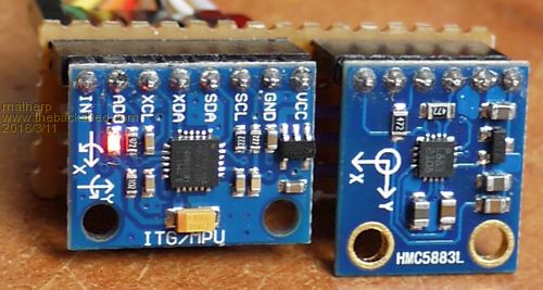
As you move the sensor around, the reading goes all over the place. Here in Tassie the magnetic field arrives at an angle of 71 degrees from horisontal. If I move my sensor so the X field is maximum and the other 2 minimum, The X arrow is pointing up at 71 degrees. The other 2 are at right angles to the field so should remain at zero as I rotate the sensors. In North Australia, it's 40 degrees and London, abut 66 degrees. The sensor has 3 sensors at right angles and you need to use all three to find the true direction of the mag field in 3D. Then, a gravitational sensor to know which way is up will help. You should be able to find an app for your phone that gives the 3 sensor readings. Jim VK7JH MMedit |
||||
Lou Senior Member Joined: 01/02/2014 Location: United StatesPosts: 229 |
Does anyone know if this chip can be used as a Gauss/magnetometer as the post name implies ?? I looked at Honeywell's data sheets and couldn't find any info or app notes on it other than "12-Bit ADC Coupled with Low Noise AMR Sensors Achieves 2 milli-gauss Field resolution in �8 Gauss Fields". I found a break out board at URL=https://www.sparkfun.com/products/10530. (Sorry, couldn't get the hyperlink to work.) Lou Microcontrollers - the other white meat |
||||
palcal Guru Joined: 12/10/2011 Location: AustraliaPosts: 2039 |
@WW Just as a matter of interest I found out what was causing the erratic readings on the bench in my workshop. I have a small desk fan on the bench and although it was about 500mm from the compass module it was causing it to jump all over the place. Paul "It is better to be ignorant and ask a stupid question than to be plain Stupid and not ask at all" |
||||
| WhiteWizzard Guru Joined: 05/04/2013 Location: United KingdomPosts: 2991 |
@palcal That will teach you to live in a hot country!! 
Mind you, I bet a heater (as we would need), would have the same affect 
Thanks for updating this thread with your findings. |
||||
| TassyJim Guru Joined: 07/08/2011 Location: AustraliaPosts: 6543 |
Speaking of which, this program draws a compass needle and gives bearing an the 3 components. It requires a ILI9341 in portrait mode. The HMC5883L is oriented with the x axis pointing 'ahead' or 'up' and the y axis to the left. ' OPTION LCDPANEL controller, orientation, D/C pin, reset pin [,CS pin]
' OPTION LCDPANEL ILI9341, RP, 4,5,6 ' OPTION TOUCH T_CS pin, T_IRQ pin ' OPTION TOUCH 7,2 ' GUI CALIBRATE OPTION EXPLICIT OPTION CLOCKTRIM -4 DIM buf(6) DIM HMC5883L_i2c = &h1e DIM HMC5883_MAGGAIN_1_3 = &h20' +/- 1.3 DIM HMC5883_MAGGAIN_1_9 = &h40' +/- 1.9 DIM HMC5883_MAGGAIN_2_5 = &h60' +/- 2.5 DIM HMC5883_MAGGAIN_4_0 = &h80' +/- 4.0 DIM HMC5883_MAGGAIN_4_7 = &hA0' +/- 4.7 DIM HMC5883_MAGGAIN_5_6 = &hC0' +/- 5.6 DIM HMC5883_MAGGAIN_8_1 = &hE0' +/- 8.1 DIM hmc5883_Gauss_LSB_XY DIM hmc5883_Gauss_LSB_Z DIM GAUSS_TO_MICROTESLA = 100 DIM magGain = HMC5883_MAGGAIN_4_7 DIM xo, yo, ro, xt, yt, zt DIM x,y,z,r, xa,ya,xao,yao, heading xo = MM.HRES/2 yo = MM.VRES/2 xao = xo : yao = yo IF xo > yo THEN ro = yo-10 ELSE ro = xo-10 ENDIF SELECT CASE magGain CASE HMC5883_MAGGAIN_1_3 hmc5883_Gauss_LSB_XY = 1100 hmc5883_Gauss_LSB_Z = 980 CASE HMC5883_MAGGAIN_1_9 hmc5883_Gauss_LSB_XY = 855 hmc5883_Gauss_LSB_Z = 760 CASE HMC5883_MAGGAIN_2_5 hmc5883_Gauss_LSB_XY = 670 hmc5883_Gauss_LSB_Z = 600 CASE HMC5883_MAGGAIN_4_0 hmc5883_Gauss_LSB_XY = 450 hmc5883_Gauss_LSB_Z = 400 CASE HMC5883_MAGGAIN_4_7 hmc5883_Gauss_LSB_XY = 400 hmc5883_Gauss_LSB_Z = 255 CASE HMC5883_MAGGAIN_5_6 hmc5883_Gauss_LSB_XY = 330 hmc5883_Gauss_LSB_Z = 295 CASE HMC5883_MAGGAIN_8_1 hmc5883_Gauss_LSB_XY = 230 hmc5883_Gauss_LSB_Z = 205 CASE ELSE magGain = HMC5883_MAGGAIN_4_7 hmc5883_Gauss_LSB_XY = 400 hmc5883_Gauss_LSB_Z = 255 END SELECT CLS FONT 1,3 SETPIN 26,DOUT ' display brightness PIN(26)=1 SETTICK 300, compass CIRCLE xo, yo, ro+5,2,1,RGB(255,255,0) I2C OPEN 100,100 ' init hmc5883 I2C WRITE HMC5883L_i2c, 0, 2, &h00, &h70 '8-average, 15 Hz default, normal measurement I2C WRITE HMC5883L_i2c, 0, 2, &h01, magGain 'Gain=5, or any other desired gain I2C WRITE HMC5883L_i2c, 0, 2, &h02, &h01 'Single-measurement mode DO LOOP I2C CLOSE END SUB compass I2C WRITE HMC5883L_i2c, 0, 2, &h02, &h01 'Single-measurement mode PAUSE 6 I2C READ HMC5883L_i2c, 0, 6, buf(0) 'Read all 6 bytes x = buf(0) * 256 + buf(1) IF x >= &h8000 THEN x = x - 65536 ' Convert three 16-bit 2's compliment z = buf(2) * 256 + buf(3) ' hex values to decimal values and IF z >= &h8000 THEN z = z - 65536 ' assign to X, Z, Y, respectively y = buf(4) * 256 + buf(5) IF y >= &h8000 THEN y = y - 65536 xt = x /hmc5883_Gauss_LSB_XY * GAUSS_TO_MICROTESLA yt = y / hmc5883_Gauss_LSB_XY * GAUSS_TO_MICROTESLA zt = z / hmc5883_Gauss_LSB_Z * GAUSS_TO_MICROTESLA heading = INT(DEG(Atn2(y,x))+.5) r = SQR(x^2 + y^2) xa = x / r *ro ya = y / r *ro LINE xo+yao,yo+xao,xo,yo,1,RGB(0,0,0) ' delete old lines LINE xo-yao,yo-xao,xo,yo,1,RGB(0,0,0) LINE xo+ya,yo+xa,xo,yo,1,RGB(255,255,0) LINE xo-ya,yo-xa,xo,yo,1,RGB(255,0,0) TEXT xo,yo," "+STR$(heading)+" ",CM xao = xa yao = ya 'PRINT xa,ya,heading TEXT xo, MM.VRES-20, " "+STR$(xt,3,2)+" "+STR$(yt,3,2)+" "+STR$(zt,3,2)+" ",CM,1,1 END SUB FUNCTION atn2(y,x) IF x > 0 THEN atn2 = ATN(y/x) ELSEIF y >= 0 AND x < 0 THEN atn2 = PI + ATN(y/x) ELSEIF y < 0 AND x < 0 THEN atn2 = ATN(y/x) - PI ELSEIF y > 0 AND x = 0 THEN atn2 = PI / 2 ELSEIF y < 0 AND x = 0 THEN atn2 = PI / -2 ENDIF IF atn2 < 0 THEN atn2 = atn2 + 2 * PI ENDIF END FUNCTION Jim VK7JH MMedit |
||||
| WhiteWizzard Guru Joined: 05/04/2013 Location: United KingdomPosts: 2991 |
Jim, Many thanks for posting this - something else of great interest to add to the to-do list! You mention that it requires an ILI in portrait mode. Purely out of interest, is there a reason why it won't work in landscape mode? I've only quickly run my eyes over the code and nothing obvious stands out. This could look really good on one of those round TFTs 
Thanks again . . . |
||||
| TassyJim Guru Joined: 07/08/2011 Location: AustraliaPosts: 6543 |
No big problems with landscape mode. The display of the 3 vectors may need to be relocated. With the current code, it is below the compass circle. In landscape, it will be over part of the circle. Jim VK7JH MMedit |
||||
| TassyJim Guru Joined: 07/08/2011 Location: AustraliaPosts: 6543 |
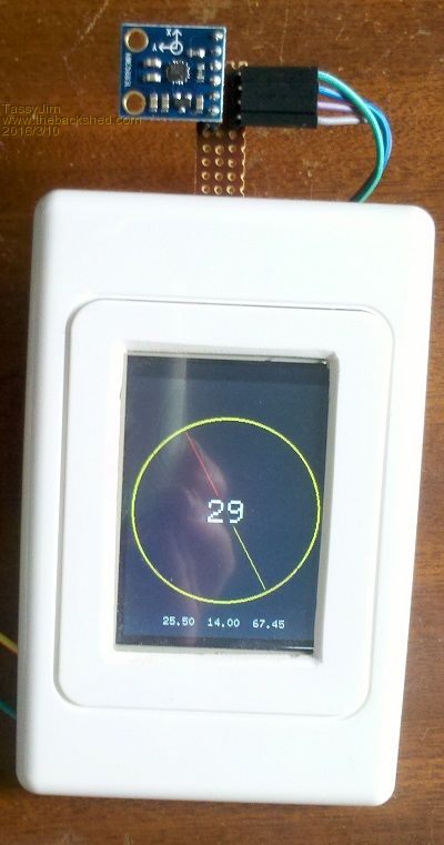
The sensor is mounted up front to be away from big hands. Red points to magnetic north and the current bearing is in the centre. The 3 numbers at the bottom are the three x, y and z vectors in uT It is fun playing with a reed switch magnet in close proximity. You can also point the 'compass' up (down in the northern hemisphere) to maximise the x reading and minimise the other two. This gives you the angle that the magnetic field is coming down at - about 70 degrees where I am. At the maximum, I read about 56uT which compares reasonable well with the expected 61uT. I will try it outside away from local interference sometime. Compass combined with accelerometer is next on the list. Edit: I found a bug in the scaling factors for the Z axis when the gain is 4.7 Line 48 to 50 should be CASE HMC5883_MAGGAIN_4_7
hmc5883_Gauss_LSB_XY = 400 hmc5883_Gauss_LSB_Z = 355 the Z axis was 255 - should be 355. Also change it in the CASE ELSE section. This gives a better maximum value for the Z axis. I copied the code from an Arduino sketch so there are a lot of lost Arduino users out there! Some code uses the same scaling for all 3 axis's. I need to do some more reading to see which is right, without calibrating. Jim VK7JH MMedit |
||||
| palcal Guru Joined: 12/10/2011 Location: AustraliaPosts: 2039 |
Hi Jim, Thanks for posting the code all seems to work except when I move to compass through 90 deg. to point East it reads 135 Deg then South is 230 and west is 295 and then back to North Zero deg. I made the changes you mentioned. Is yours reading in a linear (or should that be circular) fashion. Paul. Edit BTW where did you get the case, by far the hardest part of a project. "It is better to be ignorant and ask a stupid question than to be plain Stupid and not ask at all" |
||||
| TassyJim Guru Joined: 07/08/2011 Location: AustraliaPosts: 6543 |
I think your sensor might be upside down compared to mine. When you rotate, does the red end of the compass needle stay pointing north? After some reading, I have decided that there is no need to scale the Z axis any different to the X and Y axis's. I will update the program with a different set of gain figures. I should be able to allow for the sensor being up the other way while I am at it. Jim VK7JH MMedit |
||||
| palcal Guru Joined: 12/10/2011 Location: AustraliaPosts: 2039 |
I have mine with the chip facing up. I also meant to ask why an accelerometer with a compass. Paul "It is better to be ignorant and ask a stupid question than to be plain Stupid and not ask at all" |
||||
| TassyJim Guru Joined: 07/08/2011 Location: AustraliaPosts: 6543 |
I re-read your post. If I keep the sensor in the same location, it behaves correctly but if I hold the display in the same location and therefore move the sensor around in a circle, I get strange results. This is because I am too close to mag fields. A long power lead and standing in the clear will work better. Keeping it level makes a difference too. The 'case' is a blank electrical power outlet. I don't have the luxury of a CNC miller but the Dremmel and a shaky hand does a reasonable job of cutting the opening. This version uses what I think is the correct scaling factors: ' OPTION LCDPANEL controller, orientation, D/C pin, reset pin [,CS pin]
' OPTION LCDPANEL ILI9341, RP, 4,5,6 ' OPTION TOUCH T_CS pin, T_IRQ pin ' OPTION TOUCH 7,2 ' GUI CALIBRATE OPTION EXPLICIT OPTION CLOCKTRIM -4 option autorun on DIM buf(6) DIM HMC5883L_i2c = &h1e DIM HMC5883_MAGGAIN_088 = &h00' +/- 0.88 DIM HMC5883_MAGGAIN_1_3 = &h20' +/- 1.3 DIM HMC5883_MAGGAIN_1_9 = &h40' +/- 1.9 DIM HMC5883_MAGGAIN_2_5 = &h60' +/- 2.5 DIM HMC5883_MAGGAIN_4_0 = &h80' +/- 4.0 DIM HMC5883_MAGGAIN_4_7 = &hA0' +/- 4.7 DIM HMC5883_MAGGAIN_5_6 = &hC0' +/- 5.6 DIM HMC5883_MAGGAIN_8_1 = &hE0' +/- 8.1 DIM hmc5883_Gauss_LSB ' mG per LSb DIM mGAUSS_TO_MICROTESLA = 0.10 DIM xo, yo, ro, xt, yt, zt DIM x,y,z,r, xa,ya,xao,yao, heading DIM magGain = HMC5883_MAGGAIN_1_9 ' a good gain for general use xo = MM.HRES/2 yo = MM.VRES/2 xao = xo : yao = yo IF xo > yo THEN ro = yo-10 ELSE ro = xo-10 ENDIF SELECT CASE magGain CASE HMC5883_MAGGAIN_088 hmc5883_Gauss_LSB = 0.73 CASE HMC5883_MAGGAIN_1_3 hmc5883_Gauss_LSB = 0.92 CASE HMC5883_MAGGAIN_1_9 hmc5883_Gauss_LSB = 1.22 CASE HMC5883_MAGGAIN_2_5 hmc5883_Gauss_LSB = 1.52 CASE HMC5883_MAGGAIN_4_0 hmc5883_Gauss_LSB = 2.27 CASE HMC5883_MAGGAIN_4_7 hmc5883_Gauss_LSB = 2.56 CASE HMC5883_MAGGAIN_5_6 hmc5883_Gauss_LSB = 3.03 CASE HMC5883_MAGGAIN_8_1 hmc5883_Gauss_LSB = 4.35 CASE ELSE magGain = HMC5883_MAGGAIN_4_7 hmc5883_Gauss_LSB = 2.56 END SELECT CLS FONT 1,3 SETPIN 26,DOUT ' display brightness PIN(26)=1 SETTICK 300, compass CIRCLE xo, yo, ro+5,2,1,RGB(255,255,0) I2C OPEN 100,100 ' init hmc5883 I2C WRITE HMC5883L_i2c, 0, 2, &h00, &h70 '8-average, 15 Hz default, normal measurement I2C WRITE HMC5883L_i2c, 0, 2, &h01, magGain 'Gain=4.7, or any other desired gain I2C WRITE HMC5883L_i2c, 0, 2, &h02, &h01 'Single-measurement mode DO LOOP I2C CLOSE END SUB compass I2C WRITE HMC5883L_i2c, 0, 2, &h02, &h01 'Single-measurement mode PAUSE 6 I2C READ HMC5883L_i2c, 0, 6, buf(0) 'Read all 6 bytes x = buf(0) * 256 + buf(1) IF x >= &h8000 THEN x = x - 65536 ' Convert three 16-bit 2's compliment z = buf(2) * 256 + buf(3) ' hex values to decimal values and IF z >= &h8000 THEN z = z - 65536 ' assign to X, Z, Y, respectively y = buf(4) * 256 + buf(5) IF y >= &h8000 THEN y = y - 65536 xt = x * hmc5883_Gauss_LSB * mGAUSS_TO_MICROTESLA yt = y * hmc5883_Gauss_LSB * mGAUSS_TO_MICROTESLA zt = z * hmc5883_Gauss_LSB * mGAUSS_TO_MICROTESLA heading = INT(DEG(Atn2(y,x))+.5) r = SQR(x^2 + y^2) xa = x / r *ro ya = y / r *ro LINE xo+yao,yo+xao,xo,yo,1,RGB(0,0,0) ' delete old lines LINE xo-yao,yo-xao,xo,yo,1,RGB(0,0,0) LINE xo+ya,yo+xa,xo,yo,1,RGB(255,255,0) LINE xo-ya,yo-xa,xo,yo,1,RGB(255,0,0) TEXT xo,yo," "+STR$(heading)+" ",CM xao = xa yao = ya 'PRINT x," ",y," ",z TEXT xo, MM.VRES-20, " "+STR$(xt,3,2)+" "+STR$(yt,3,2)+" "+STR$(zt,3,2)+" ",CM,1,1 END SUB FUNCTION atn2(y,x) IF x > 0 THEN atn2 = ATN(y/x) ELSEIF y >= 0 AND x < 0 THEN atn2 = PI + ATN(y/x) ELSEIF y < 0 AND x < 0 THEN atn2 = ATN(y/x) - PI ELSEIF y > 0 AND x = 0 THEN atn2 = PI / 2 ELSEIF y < 0 AND x = 0 THEN atn2 = PI / -2 ENDIF IF atn2 < 0 THEN atn2 = atn2 + 2 * PI ENDIF END FUNCTION Jim VK7JH MMedit |
||||
| TassyJim Guru Joined: 07/08/2011 Location: AustraliaPosts: 6543 |
An accelerometer gets your tilt/inclination. Together you can calculated the mag field in 3D. We 'should' be able to end up with a compass that works on any angle. Jim VK7JH MMedit |
||||
| palcal Guru Joined: 12/10/2011 Location: AustraliaPosts: 2039 |
I had my compass outside well away from any interference when it was reading incorrectly. I also had it flat on a table so it was not at an angle. Paul. "It is better to be ignorant and ask a stupid question than to be plain Stupid and not ask at all" |
||||
| matherp Guru Joined: 11/12/2012 Location: United KingdomPosts: 11603 |
Jim Where are you getting these numbers from? The datasheet I'm looking at seems to say the scale is 390 in both cases |
||||
| palcal Guru Joined: 12/10/2011 Location: AustraliaPosts: 2039 |
With the latest code North is showing at about 40 Deg. When I rotate, the red line also moves by about 40 Deg. Paul. "It is better to be ignorant and ask a stupid question than to be plain Stupid and not ask at all" |
||||
| TassyJim Guru Joined: 07/08/2011 Location: AustraliaPosts: 6543 |
I found some Arduino code from Adafruit. Most of the other code I found on the net seemed to use it as a base so I converted it. My later code posted here uses the values from the data sheet with Z the same as X an Y. I am still not sure where the Adafruit code got its figures from seeing they had the datasheet. Jim VK7JH MMedit |
||||
| palcal Guru Joined: 12/10/2011 Location: AustraliaPosts: 2039 |
@Jim, I also see that when pointing North the heading can read either 360 Deg or 0 Deg. Should it not be one or the other. Paul. "It is better to be ignorant and ask a stupid question than to be plain Stupid and not ask at all" |
||||
| TassyJim Guru Joined: 07/08/2011 Location: AustraliaPosts: 6543 |
After: heading = INT(DEG(Atn2(yh,xh))+.5) add a line: if heading = 360 then heading = 0 I have been trying to add compensation for tilt but not very happy with the results. Two application notes from Honeywell give conflicting information. I am using a MPU6050 to get the tilt OK but the formulas for correcting the X and Y mag readings don't seem to give me acceptable answers. I think I will have to give it a rest and work on something else for a while. Jim VK7JH MMedit |
||||
| matherp Guru Joined: 11/12/2012 Location: United KingdomPosts: 11603 |
Jim Attached is a full AHRS implementation using MPU6050 and HMC5883 you may recognise some of your code in there 
The issue I'm not sure of is the relative relationship of the x, y and z axis of the two sensors in the call to the sensor fusion routine MahonyAHRSupdateMag(gx, gy, gz, ax,ay, az, -my, mx, -mz)
I'm using x=-y, y=x, z=-z and it seems OKish. I've also got a version for the MPU9250 but bizarrely this chip is also a composite of two dies with the magnetometer separate and the axis aren't aligned in it either option explicit
option default FLOAT ' ' Micromite AHRS using MPU6050 ' Original source code from kriswiner (https://github.com/kriswiner/MPU-6050) ' and Sebastion Madgwick's Open source IMU and AHRS algorithms ' ' Use TFT display in landscape mode to display position ' ' MPU6050 connections ' GND ' VCC - 3.3V ' SCL to I2C clock ' SDA to I2C data ' NCS to 3.3V (needed to force I2C) ' INT to intPin ' AD0 to GND or 3.3V (see address below) const intPin = 16 'const MPU6050_ADDRESS =&H69 ' Device address when ADO = 1 const MPU6050_ADDRESS =&H68 ' Device address when ADO = 0 ' 'Magnetometer Registers and constants const HMC5883L_I2C = &h1e const HMC5883_MAGGAIN_4_7 = &hA0' +/- 4.7 const hmc5883_Gauss_LSB_XY = 390 const hmc5883_Gauss_LSB_Z = 390 const GAUSS_TO_MICROTESLA = 100 Const HMC5883_CONFIG_A = 0 Const HMC5883_CONFIG_B = 1 Const HMC5883_MODE = 2 Const HMC5883_MSB_X = 3 Const HMC5883_LSB_X = 4 Const HMC5883_MSB_Y = 5 Const HMC5883_LSB_Y = 8 Const HMC5883_MSB_Z = 7 Const HMC5883_LSB_Z = 8 Const HMC5883_STATUS = 9 Const HMC5883_ID_A = 10 Const HMC5883_ID_B = 11 Const HMC5883_ID_C = 12 ' Gyro/accelerometer registers const SELF_TEST_X =&H0D const SELF_TEST_Y =&H0E const SELF_TEST_Z =&H0F const SELF_TEST_A =&H10 const SMPLRT_DIV =&H19 const CONFIG =&H1A const GYRO_CONFIG =&H1B const ACCEL_CONFIG =&H1C const FIFO_EN =&H23 const I2C_MST_CTRL =&H24 const I2C_SLV0_ADDR =&H25 const I2C_SLV0_REG =&H26 const I2C_SLV0_CTRL =&H27 const I2C_SLV1_ADDR =&H28 const I2C_SLV1_REG =&H29 const I2C_SLV1_CTRL =&H2A const I2C_SLV2_ADDR =&H2B const I2C_SLV2_REG =&H2C const I2C_SLV2_CTRL =&H2D const I2C_SLV3_ADDR =&H2E const I2C_SLV3_REG =&H2F const I2C_SLV3_CTRL =&H30 const I2C_SLV4_ADDR =&H31 const I2C_SLV4_REG =&H32 const I2C_SLV4_DO =&H33 const I2C_SLV4_CTRL =&H34 const I2C_SLV4_DI =&H35 const I2C_MST_STATUS =&H36 const INT_PIN_CFG =&H37 const INT_ENABLE =&H38 const DMP_INT_STATUS =&H39 ' Check DMP interrupt const INT_STATUS =&H3A const ACCEL_XOUT_H =&H3B const ACCEL_XOUT_L =&H3C const ACCEL_YOUT_H =&H3D const ACCEL_YOUT_L =&H3E const ACCEL_ZOUT_H =&H3F const ACCEL_ZOUT_L =&H40 const TEMP_OUT_H =&H41 const TEMP_OUT_L =&H42 const GYRO_XOUT_H =&H43 const GYRO_XOUT_L =&H44 const GYRO_YOUT_H =&H45 const GYRO_YOUT_L =&H46 const GYRO_ZOUT_H =&H47 const GYRO_ZOUT_L =&H48 const EXT_SENS_DATA_00 =&H49 const EXT_SENS_DATA_01 =&H4A const EXT_SENS_DATA_02 =&H4B const EXT_SENS_DATA_03 =&H4C const EXT_SENS_DATA_04 =&H4D const EXT_SENS_DATA_05 =&H4E const EXT_SENS_DATA_06 =&H4F const EXT_SENS_DATA_07 =&H50 const EXT_SENS_DATA_08 =&H51 const EXT_SENS_DATA_09 =&H52 const EXT_SENS_DATA_10 =&H53 const EXT_SENS_DATA_11 =&H54 const EXT_SENS_DATA_12 =&H55 const EXT_SENS_DATA_13 =&H56 const EXT_SENS_DATA_14 =&H57 const EXT_SENS_DATA_15 =&H58 const EXT_SENS_DATA_16 =&H59 const EXT_SENS_DATA_17 =&H5A const EXT_SENS_DATA_18 =&H5B const EXT_SENS_DATA_19 =&H5C const EXT_SENS_DATA_20 =&H5D const EXT_SENS_DATA_21 =&H5E const EXT_SENS_DATA_22 =&H5F const EXT_SENS_DATA_23 =&H60 const MOT_DETECT_STATUS =&H61 const I2C_SLV0_DO =&H63 const I2C_SLV1_DO =&H64 const I2C_SLV2_DO =&H65 const I2C_SLV3_DO =&H66 const I2C_MST_DELAY_CTRL =&H67 const SIGNAL_PATH_RESET =&H68 const MOT_DETECT_CTRL =&H69 const USER_CTRL =&H6A ' Bit 7 enable DMP, bit 3 reset DMP const PWR_MGMT_1 =&H6B ' Device defaults to the SLEEP mode const PWR_MGMT_2 =&H6C const DMP_BANK =&H6D ' Activates a specific bank in the DMP const DMP_RW_PNT =&H6E ' Set read/write pointer to a specific start address in specified DMP bank const DMP_REG =&H6F ' Register in DMP from which to read or to which to write const DMP_REG_1 =&H70 const DMP_REG_2 =&H71 const FIFO_COUNTH =&H72 const FIFO_COUNTL =&H73 const FIFO_R_W =&H74 const WHO_AM_I_MPU6050 =&H75 ' Should return =&H71 const XA_OFFSET_H =&H77 const XA_OFFSET_L =&H78 const YA_OFFSET_H =&H7A const YA_OFFSET_L =&H7B const ZA_OFFSET_H =&H7D const ZA_OFFSET_L =&H7E const AFS_2G = 0 const AFS_4G =1 const AFS_8G =2 const AFS_16G =3 const GFS_250DPS = 0 const GFS_500DPS =1 const GFS_1000DPS =2 const GFS_2000DPS =3 const MFS_14BITS = 0' 0.6 mG per LSB const MFS_16BITS =1' 0.15 mG per LSB const sampleFreq=12.0 ' sample frequency in Hz const twoKpDef=1 ' 2 * proportional gain const twoKiDef=0.0 ' 2 * integral gain ' ' Global Variable definitions ' dim float twoKp = twoKpDef ' 2 * proportional gain (Kp) dim float twoKi = twoKiDef ' 2 * integral gain (Ki) dim float q0 = 1.0, q1 = 0.0, q2 = 0.0, q3 = 0.0 ' quaternion of sensor frame relative to auxiliary frame dim float integralFBx = 0.0, integralFBy = 0.0, integralFBz = 0.0 ' integral error terms scaled by Ki DIM INTEGER Mmode = &H02 DIM INTEGER Gscale = GFS_250DPS DIM INTEGER Ascale = AFS_8G DIM INTEGER Mscale = MFS_16BITS ' Choose either 14-bit or 16-bit magnetometer resolution DIM float magcount(6) ' 2 for 8 Hz, 6 for 100 Hz continuous magnetometer data read DIM FLOAT MagCalibration(2),magbias(2),accelCount(2),gyrocount(2),gRes,mRes,aRes dim float ax,ay,az,gx,gy,gz,mx,my,mz,SelfTest(5),gyroBias(2),accelBias(2),fmult,mmult(2) dim float pitch,yaw,roll dim integer gdata(13),temp% DIM ID$ length 3 ' ' Setup ' i2c open 400,1000 setpin intPin,DIN pause 100 writeByte(MPU6050_ADDRESS,PWR_MGMT_1,&H80) pause 500 initMPU6050 temp%=readByte(MPU6050_ADDRESS,WHO_AM_I_MPU6050) if temp%<>&H68 then Print "MPU6050 not found" end endif readByteString(HMC5883L_I2C,HMC5883_ID_A,3,ID$) if ID$<>"H43" then Print "HMC5883 not found" end endif print "Internal temperature is ",readTempData() initHMC5883 getAres getGres getMres fmult=gRes*PI/180.0 magbias(0) = 0' ' User environmental x-axis correction in MICROTESLA magbias(1) = 0' ' User environmental y-axis correction in MICROTESLA magbias(2) = 0' ' User environmental z-axis correction in MICROTESLA timer=0 ' temp%=0 do readMPU6050andmag(0) MahonyAHRSupdateMag(gx, gy, gz, ax,ay, az, -my, mx, -mz) yaw = atan2(2.0 * (q1 * q2 + q0 * q3), q0 * q0 + q1 * q1 - q2 * q2 - q3 * q3) pitch = -asin(2.0 * (q1 * q3 - q0 * q2)) roll = atan2(2.0 * (q0 * q1 + q2 * q3), q0 * q0 - q1 * q1 - q2 * q2 + q3 * q3) pitch=deg(pitch) yaw = deg(yaw) yaw = yaw + 0.719' Declination at Saffron walden = 0.719 deg East roll = deg(roll) if (temp% mod sampleFreq) = 0 then print "Pitch = "+str$(pitch,3,2," ")+" Yaw = "+str$(yaw,3,2," ")+" Roll = "+str$(roll,3,2," ") if timer>1000/samplefreq then print "Sample frequency too high - reduce by factor of ",timer/(1000/sampleFreq) end else do loop while timer<1000/sampleFreq timer = 0 temp%=temp%+1 endif loop end ' sub readMPU6050andmag(offset%) if pin(intPin) then readBytes(MPU6050_ADDRESS, ACCEL_XOUT_H, 14, gData()) readAccelData(gData(),accelCount()) ' Convert the x/y/z adc values ' Now we'll calculate the accleration value into actual g's ax = accelCount(0)*aRes' - accelBias(0)' get actual g value, this depends on scale being set ay = accelCount(1)*aRes' - accelBias(1) az = accelCount(2)*aRes' - accelBias(2) ' print "Acc X="+str$(ax,3,2," ")+" Y="+str$(ay,3,2," ")+" Z="+str$(az,3,2," ") readGyroData(gData(),gyroCount())' Convert the x/y/z adc values ' Calculate the gyro value into actual radians per second gx = gyroCount(0)*fmult' get actual gyro value, this depends on scale being set gy = gyroCount(1)*fmult' gz = gyroCount(2)*fmult' ' print "Rot X="+str$(gx,3,2," ")+" Y="+str$(gy,3,2," ")+" Z="+str$(gz,3,2," ") readMagData(magCount())' Read the x/y/z adc values ' Calculate the magnetometer values in milliGauss ' Include factory calibration per data sheet and user environmental corrections mx = magCount(0) - magbias(0)' get actual magnetometer value, this depends on scale being set my = magCount(1) - magbias(1) mz = magCount(2) - magbias(2) ' print "Mag X="+str$(mx,3,2," ")+" Y="+str$(my,3,2," ")+" Z="+str$(mz,3,2," ") endif end sub ' sub initMPU6050 LOCAL INTEGER c ' wake up device writeByte(MPU6050_ADDRESS, PWR_MGMT_1, &H00) ' Clear sleep mode bit (6), enable all sensors pause 100 ' Wait for all registers to reset ' get stable time source writeByte(MPU6050_ADDRESS, PWR_MGMT_1, &H01) ' Auto select clock source to be PLL gyroscope reference if ready else pause 200 ' Configure Gyro and Thermometer ' Disable FSYNC and set thermometer and gyro bandwidth to 41 and 42 Hz, respectively ' minimum delay time for this setting is 5.9 ms, which means sensor fusion update rates cannot ' be higher than 1 / 0.0059 = 170 Hz ' DLPF_CFG = bits 2:0 = 011 this limits the sample rate to 1000 Hz for both ' With the MPU6050, it is possible to get gyro sample rates of 32 kHz (!), 8 kHz, or 1 kHz writeByte(MPU6050_ADDRESS, CONFIG, &H03) ' Set sample rate = gyroscope output rate/(1 + SMPLRT_DIV) writeByte(MPU6050_ADDRESS, SMPLRT_DIV, &H04) ' Use a 200 Hz rate a rate consistent with the filter update rate ' Set gyroscope full scale range ' Range selects FS_SEL and AFS_SEL are 0 - 3, so 2-bit values are left-shifted into positions 4:3 c = readByte(MPU6050_ADDRESS, GYRO_CONFIG) c=c AND &B11100100 c = c OR (Gscale << 3) ' Set full scale range for the gyro writeByte(MPU6050_ADDRESS, GYRO_CONFIG, c ) ' Write new GYRO_CONFIG value to register ' Set accelerometer full-scale range configuration c = readByte(MPU6050_ADDRESS, ACCEL_CONFIG) c=c AND &B11100111 c = c OR (Ascale << 3) ' Set full scale range for the accelerometer writeByte(MPU6050_ADDRESS, ACCEL_CONFIG, c) ' Write new ACCEL_CONFIG register value ' Set accelerometer sample rate configuration ' It is possible to get a 4 kHz sample rate from the accelerometer by choosing 1 for ' accel_fchoice_b bit (3) in this case the bandwidth is 1.13 kHz ' The accelerometer, gyro, and thermometer are set to 1 kHz sample rates, ' but all these rates are further reduced by a factor of 5 to 200 Hz because of the SMPLRT_DIV setting ' Configure Interrupts and Bypass Enable ' Set interrupt pin active high, push-pull, hold interrupt pin level HIGH until interrupt cleared, ' clear on read of INT_STATUS, and enable I2C_BYPASS_EN so additional chips ' can join the I2C bus and all can be controlled by the Arduino as master writeByte(MPU6050_ADDRESS, INT_PIN_CFG, &H22) writeByte(MPU6050_ADDRESS, INT_ENABLE, &H01) ' Enable data ready (bit 0) interrupt writeByte(MPU6050_ADDRESS, USER_CTRL, &H05) pause 100 end sub sub initHMC5883() I2C WRITE HMC5883L_i2c, 0, 2, HMC5883_CONFIG_A, &h74 '8-average, 30 Hz, normal measurement I2C WRITE HMC5883L_i2c, 0, 2, HMC5883_CONFIG_B, HMC5883_MAGGAIN_4_7 'Gain=4, or any other desired gain I2C WRITE HMC5883L_i2c, 0, 2, HMC5883_MODE, &h01 'Single-measurement mode end sub sub writeByte(address%,reg%,value%) i2c write address%,0,2,reg%,value% end sub ' function readByte(address%,reg%) as integer local r% i2c write address%,1,1,reg% i2c read address%,0,1,readByte end function ' sub readBytes(address%,reg%,n%,a%()) i2c write address%,1,1,reg% i2c read address%,0,n%,a%() end sub ' sub readByteString(address%,reg%,n%,s$) i2c write address%,1,1,reg% i2c read address%,0,n%,S$ end sub ' sub getMres select case Mscale ' Possible magnetometer scales (and their register bit settings) are: ' 14 bit resolution (0) and 16 bit resolution (1) case MFS_14BITS mRes = 10.*4912./8190. ' Proper scale to return milliGauss case MFS_16BITS mRes = 10.*4912./32760.0 ' Proper scale to return milliGauss end select end sub ' sub getGres select case Gscale ' Possible gyro scales (and their register bit settings) are: '250 DPS (00), 500 DPS (01), 1000 DPS (10), and 2000 DPS (11). ' Here's a bit of an algorith to calculate DPS/(ADC tick) based on that 2-bit value: case GFS_250DPS gRes = 250.0/32768.0 case GFS_500DPS gRes = 500.0/32768.0 case GFS_1000DPS gRes = 1000.0/32768.0 case GFS_2000DPS gRes = 2000.0/32768.0 end select end sub ' sub getAres select case Ascale ' Possible accelerometer scales (and their register bit settings) are: ' 2 Gs (00), 4 Gs (01), 8 Gs (10), and 16 Gs (11). ' Here's a bit of an algorith to calculate DPS/(ADC tick) based on that 2-bit value: case AFS_2G aRes = 2.0/32768.0 case AFS_4G aRes = 4.0/32768.0 case AFS_8G aRes = 8.0/32768.0 case AFS_16G: aRes = 16.0/32768.0 end select end sub ' sub readAccelData(rawData() as integer,destination() as float) destination(0) = sint16((rawData(0) << 8) OR rawData(1)) ' Turn the MSB and LSB into a signed 16-bit value destination(1) = sint16((rawData(2) << 8) OR rawData(3)) destination(2) = sint16((rawData(4) << 8) OR rawData(5)) end sub ' sub readGyroData(rawData() as integer,destination() as float) destination(0) = sint16((rawData(8) << 8) OR rawData(9)) 'Turn the MSB and LSB into a signed 16-bit value destination(1) = sint16((rawData(10) << 8) OR rawData(11)) destination(2) = sint16((rawData(12) << 8) OR rawData(13)) end sub ' sub readMagData(destination() as float) local integer rawData(5)' x/y/z gyro register data, ST2 register stored here, must read ST2 at end of data acquisition readBytes(HMC5883L_I2C, HMC5883_MSB_X, 6, rawData())' Read the six raw data destination(0) = (sint16((rawData(0) << 8) OR rawData(1)))/hmc5883_Gauss_LSB_XY * GAUSS_TO_MICROTESLA ' Turn the MSB and LSB into a signed 16-bit value destination(2) = (sint16((rawData(2) << 8) OR rawData(3)))/hmc5883_Gauss_LSB_Z * GAUSS_TO_MICROTESLA ' Data stored as little Endian destination(1) = (sint16((rawData(4) << 8) OR rawData(5)))/hmc5883_Gauss_LSB_XY * GAUSS_TO_MICROTESLA I2C WRITE HMC5883L_i2c, 0, 2, HMC5883_MODE, &h01 'Single-measurement mode end sub ' function readTempData() as float local integer rawData(1) ' x/y/z gyro register data stored here readBytes(MPU6050_ADDRESS, TEMP_OUT_H, 2, rawData()) ' Read the two raw data registers sequentially into data array readTempData=sint16((rawData(0) << 8) OR rawData(1)) / 340 + 36.53 end function ' FUNCTION sint16(x as integer) as float ' convert to signed 16 bit number local a%=x IF a% AND &H8000 then a%=a% OR &HFFFFFFFFFFFF0000 sint16 = a% END FUNCTION ' FUNCTION iint16(x as integer) as integer ' convert to signed 16 bit number local a%=x IF a% AND &H8000 then a%=a% OR &HFFFFFFFFFFFF0000 iint16 = a% END FUNCTION ' ' '===================================================================================================== ' MahonyAHRS.c '===================================================================================================== ' ' Madgwick's implementation of Mayhony's AHRS algorithm. ' See: http://www.x-io.co.uk/node/8#open_source_ahrs_and_imu_algorithms ' ' Date Author Notes ' 29/09/2011 SOH Madgwick Initial release ' 02/10/2011 SOH Madgwick Optimised for reduced CPU load ' '--------------------------------------------------------------------------------------------------- ' AHRS algorithm update sub MahonyAHRSupdateMag(gx as float, gy as float, gz as float, ax as float, ay as float, az as float, mx as float, my as float, mz as float) local float recipNorm, q0q0, q0q1, q0q2, q0q3, q1q1, q1q2, q1q3, q2q2, q2q3, q3q3 local float hx, hy, bx, bz, halfvx, halfvy, halfvz, halfwx, halfwy, halfwz local float halfex, halfey, halfez, qa, qb, qc ' Compute feedback only if accelerometer measurement valid (avoids NaN in accelerometer normalisation) if(((ax <> 0.0) OR (ay <> 0.0) OR (az <> 0.0))) then ' Normalise accelerometer measurement recipNorm = invSqrt(ax * ax + ay * ay + az * az) ax = ax * recipNorm ay = ay * recipNorm az = az * recipNorm ' Normalise magnetometer measurement recipNorm = invSqrt(mx * mx + my * my + mz * mz) mx = mx * recipNorm my = my * recipNorm mz = mz * recipNorm ' Auxiliary variables to avoid repeated arithmetic q0q0 = q0 * q0 q0q1 = q0 * q1 q0q2 = q0 * q2 q0q3 = q0 * q3 q1q1 = q1 * q1 q1q2 = q1 * q2 q1q3 = q1 * q3 q2q2 = q2 * q2 q2q3 = q2 * q3 q3q3 = q3 * q3 ' Reference direction of Earth's magnetic field hx = 2.0 * (mx * (0.5 - q2q2 - q3q3) + my * (q1q2 - q0q3) + mz * (q1q3 + q0q2)) hy = 2.0 * (mx * (q1q2 + q0q3) + my * (0.5 - q1q1 - q3q3) + mz * (q2q3 - q0q1)) bx = sqr(hx * hx + hy * hy) bz = 2.0 * (mx * (q1q3 - q0q2) + my * (q2q3 + q0q1) + mz * (0.5 - q1q1 - q2q2)) ' Estimated direction of gravity and magnetic field halfvx = q1q3 - q0q2 halfvy = q0q1 + q2q3 halfvz = q0q0 - 0.5 + q3q3 halfwx = bx * (0.5 - q2q2 - q3q3) + bz * (q1q3 - q0q2) halfwy = bx * (q1q2 - q0q3) + bz * (q0q1 + q2q3) halfwz = bx * (q0q2 + q1q3) + bz * (0.5 - q1q1 - q2q2) ' Error is sum of cross product between estimated direction and measured direction of field vectors halfex = (ay * halfvz - az * halfvy) + (my * halfwz - mz * halfwy) halfey = (az * halfvx - ax * halfvz) + (mz * halfwx - mx * halfwz) halfez = (ax * halfvy - ay * halfvx) + (mx * halfwy - my * halfwx) ' Compute and apply integral feedback if enabled if twoKi > 0.0 THEN integralFBx = integralFBx + twoKi * halfex * (1.0 / sampleFreq) ' integral error scaled by Ki integralFBy = integralFBy + twoKi * halfey * (1.0 / sampleFreq) integralFBz = integralFBz * twoKi * halfez * (1.0 / sampleFreq) gx = gx + integralFBx ' apply integral feedback gy = gy + integralFBy gz = gz + integralFBz else integralFBx = 0.0 ' prevent integral windup integralFBy = 0.0 integralFBz = 0.0 ENDIF ' Apply proportional feedback gx = gx + twoKp * halfex gy = gy + twoKp * halfey gz = gz + twoKp * halfez endif ' Integrate rate of change of quaternion gx = gx * (0.5 * (1.0 / sampleFreq)) ' pre-multiply common factors gy = gy * (0.5 * (1.0 / sampleFreq)) gz = gz * (0.5 * (1.0 / sampleFreq)) qa = q0 qb = q1 qc = q2 q0 = q0 +(-qb * gx - qc * gy - q3 * gz) q1 = q1 +(qa * gx + qc * gz - q3 * gy) q2 = q2 +(qa * gy - qb * gz + q3 * gx) q3 = q3 +(qa * gz + qb * gy - qc * gx) ' Normalise quaternion recipNorm = invSqrt(q0 * q0 + q1 * q1 + q2 * q2 + q3 * q3) q0 = q0 * recipNorm q1 = q1 * recipNorm q2 = q2 * recipNorm q3 = q3 * recipNorm end sub sub MahonyAHRSupdate(gx as float, gy as float, gz as float, ax as float, ay as float, az as float) local float recipNorm local float halfvx, halfvy, halfvz local float halfex, halfey, halfez local float qa, qb, qc ' Compute feedback only if accelerometer measurement valid (avoids NaN in accelerometer normalisation) if(((ax <> 0.0) OR (ay <> 0.0) OR (az <> 0.0))) then ' Normalise accelerometer measurement recipNorm = invSqrt(ax * ax + ay * ay + az * az) ax = ax * recipNorm ay = ay * recipNorm az = az * recipNorm ' Estimated direction of gravity and vector perpendicular to magnetic flux halfvx = q1 * q3 - q0 * q2 halfvy = q0 * q1 + q2 * q3 halfvz = q0 * q0 - 0.5 + q3 * q3 ' Error is sum of cross product between estimated and measured direction of gravity halfex = (ay * halfvz - az * halfvy) halfey = (az * halfvx - ax * halfvz) halfez = (ax * halfvy - ay * halfvx) ' Compute and apply integral feedback if enabled if twoKi > 0.0 THEN integralFBx = integralFBx + twoKi * halfex * (1.0 / sampleFreq) ' integral error scaled by Ki integralFBy = integralFBy + twoKi * halfey * (1.0 / sampleFreq) integralFBz = integralFBz * twoKi * halfez * (1.0 / sampleFreq) gx = gx + integralFBx ' apply integral feedback gy = gy + integralFBy gz = gz + integralFBz else integralFBx = 0.0 ' prevent integral windup integralFBy = 0.0 integralFBz = 0.0 ENDIF ' Apply proportional feedback gx = gx + twoKp * halfex gy = gy + twoKp * halfey gz = gz + twoKp * halfez endif ' Integrate rate of change of quaternion gx = gx * (0.5 * (1.0 / sampleFreq)) ' pre-multiply common factors gy = gy * (0.5 * (1.0 / sampleFreq)) gz = gz * (0.5 * (1.0 / sampleFreq)) qa = q0 qb = q1 qc = q2 q0 = q0 +(-qb * gx - qc * gy - q3 * gz) q1 = q1 +(qa * gx + qc * gz - q3 * gy) q2 = q2 +(qa * gy - qb * gz + q3 * gx) q3 = q3 +(qa * gz + qb * gy - qc * gx) ' Normalise quaternion recipNorm = invSqrt(q0 * q0 + q1 * q1 + q2 * q2 + q3 * q3) q0 = q0 * recipNorm q1 = q1 * recipNorm q2 = q2 * recipNorm q3 = q3 * recipNorm end sub FUNCTION atan2(y as float,x as float) as float IF x > 0 THEN atan2 = ATN(y/x) ELSEIF y >= 0 AND x < 0 THEN atan2 = PI + ATN(y/x) ELSEIF y < 0 AND x < 0 THEN atan2 = ATN(y/x) - PI ELSEIF y > 0 AND x = 0 THEN atan2 = PI / 2 ELSEIF y < 0 AND x = 0 THEN atan2 = PI / -2 ENDIF IF atan2 < 0 THEN atan2 = atan2 + 2 * PI ENDIF END FUNCTION function asin(x!) as float asin=atn(x!/sqr(1-x!*x!)) end function function invsqrt(x!) as float invsqrt=x! ^ -0.5 end function |
||||
| The Back Shed's forum code is written, and hosted, in Australia. | © JAQ Software 2026 |
