
|
|
Forum Index : Microcontroller and PC projects : Triggerd PWM..
| Author | Message | ||||
Chopperp Guru Joined: 03/01/2018 Location: AustraliaPosts: 1123 |
Yeh, can be dangerous. Important to have safety measures in place. The important bits of the Radar (cooling fans etc), were fed from phase & voltage protection circuitry. ChopperP |
||||
| Zonker Guru Joined: 18/08/2012 Location: United StatesPosts: 772 |
The circuits that were used back in the 60s and 70s consisted of Opto's to reset an R/C circuit and a comparitor circuit that drove the gate driver. A control voltage would be applied to select the phase angle.. This would work ok for generating DC voltages for 3 phase setups that would supply current in only one direction... They would then use Semikron SCR/Diode modules to form the main rectifier assembly... 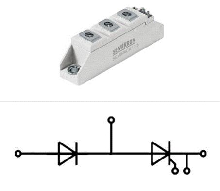 Nowadays, they use dual SCR modules to form a "6 pulse" system so that the voltage and current can go positive or negative.. When doing battery testing, they wanted to be able to regenerate the discharge current back onto the AC line... This is where it gets tricky working in the third and fourth quadrants... |
||||
| Chopperp Guru Joined: 03/01/2018 Location: AustraliaPosts: 1123 |
Very difficult to understand as well (for me anyway) especially the regeneration when the battery volts is lower than the AC or DC input. For radio modulation stuff, Q.A.M. is much fun, particularly up around 4096-QAM where there's 12 bits per carrier cycle (I think) ChopperP |
||||
| Zonker Guru Joined: 18/08/2012 Location: United StatesPosts: 772 |
So.. I was wanting to do this with timer capture hardware inside the MPU but it can't be done on the MM that way I have heard... OK... It's just I would like a 16 bit resolution of the timer (65535)... In the examples, one uses the settick command but at 1ms resolution would be kind of "choppy" on the selections... 50hz is 20ms per whole cycle (16 for 60hz)... so, for 50hz the center point near the positive cycle zero volts point would be 10ms.. only 10 points could be selected... bummer for DC voltage control... The second way given seems better... The PULSE command would be better at doing the job, except Geoff would need to make a change in the way it can behave... Instead of just "flipping states" when it starts, I would need to say what state to start with when triggered, (1 or 0)... Let's say when the gate driver enable goes high the SCR will trigger.. So, I need to start the PULSE command with "0" and then switch states on completion... Also, it needs to be able to call another SUB to link to the "loop chain" of actions and checks being done at the same time... Returning the selected pin to 0 would be the first thing to do... The resolution is still not as good as needed, but I think if we could get the firmware changes, it would be worth trying to tinker a 3 phase DC supply test rig set up..  I can get every thing needed at work... I can get every thing needed at work...I hope all my thinking is correct here, but maybe this can be done without any firmware updates... Still scratchin..!!  As always, feedback is welcome... |
||||
| Warpspeed Guru Joined: 09/08/2007 Location: AustraliaPosts: 4406 |
Timer input capture is ideal, because you can program that to work on either edge. But you are going to need three input capture channels for three phase. And if you also have three output compare channels, its then dead easy to set up any delay with maybe 1uS resolution, and make the delay the same on all three channels. Then you are going to need at least one analog input for voltage feedback, and perhaps a second analog input for current limit. Something like a Motorola 68HC11 or 68HC12 has all that. Cheers, �Tony. |
||||
| Zonker Guru Joined: 18/08/2012 Location: United StatesPosts: 772 |
Agreed.. I would also like a "six pack" of them for the 6 pulse system needed... And it would all be done with hardware and interrupts... If they are 16 bit timers, I think the output voltage could be controlled nicely..  I would also need missing phase detection and rotation correction so that any combination of wiring errors wouldn't cause problems... I wonder if there as a "basic" firmware core for the 6812 MPU..?? I sure would miss Geoff's working environment..!! EDIT: Looking at the data sheet... Nice...  With 10 bit A/D's for sensing, this could just do the trick..!  And, I think I found a "Basic" compiler for it... More head scratching needed... |
||||
| Warpspeed Guru Joined: 09/08/2007 Location: AustraliaPosts: 4406 |
The input captures can be set to respond to either edge, or both edges, and of course generate an interrupt as well. There is no substitute for starting out with a processor that has sufficient resources to do the job very easily without having to resort to desperate software tricks. Cheers, �Tony. |
||||
| Zonker Guru Joined: 18/08/2012 Location: United StatesPosts: 772 |
OK... Here is the ZIP file for the basic compiler.. 2018-05-25_144631_sbasic11.zip Looking over the LIB's and stuff... Thank you fine Sir for the proper head kicking..! Oops, forgot the HC12 assembler... 2018-05-25_144948_as12rel.zip Now off to check out some prototype boards... |
||||
| Chopperp Guru Joined: 03/01/2018 Location: AustraliaPosts: 1123 |
@Geoff. I tried this but could not get the PWM to reset as expected. It just kept free running. I was able to vary the pulse width OK though. (Ver 5.04.08) I tried using a PWM 1, STOP command before issuing a new PWM command which worked but it would not accept any new parameters unless the program was stopped. Re further suggestions:- I found that there was too much jitter in the PULSE command above about 2.9mS. This also applied to the SETTICK commands. The only way I could get a good steady trigger pulse was to use 4 x PULSE commands, one after the other, keeping the width below 3mS. The only problem here is with maximum delay, there is no time left for the program to do anything else before the next interrupt is due. Interrupt latency was a small issue though. BTW, you need 100 / 120Hz trigger pulses for 50 / 60Hz single phase mains which makes things more difficult. 3 phase is out of the question I think. ChopperP |
||||
| matherp Guru Joined: 11/12/2012 Location: United KingdomPosts: 11166 |
Can you explain the requirement clearly. I'm pretty certain all the hooks are in MMBasic to do this with a pretty simple CFunction |
||||
| Chopperp Guru Joined: 03/01/2018 Location: AustraliaPosts: 1123 |
Hi matherp, My requirements are simply for a trigger pulse for an SCR generated between ~ 1mS & 10mS after a 10mS trigger interrupt. The pulse delay needs to be proportional to an input voltage from 0 to ~3V. The photo shows a short pulse being generated triggered after about 3.5mS from the zero point in the rectified AC wave. (We have flat topped Mains here in Aussie land). The pulse was generated using several PULSE commands which is not ideal. Zonker wants to control 3 phase which probably means 3 pulses every ~8.3mS (60Hz), each shifted 120 deg in phase. Hope this clarifies things a bit. Thanks for any help you are able to offer. 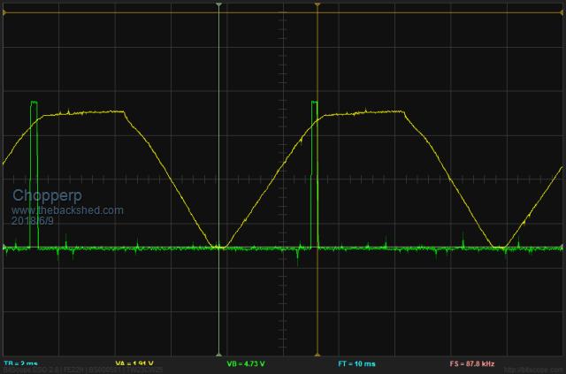 ChopperP |
||||
| matherp Guru Joined: 11/12/2012 Location: United KingdomPosts: 11166 |
In order to make this work there are a couple of pre-requisites. If these work for you let me know and I'll have a play 1. If you are using a MM2 then the code will be incompatible with also using IR input 2. The trigger input must be on a specific pin (15 if 28-pin MM2) It will make things easier if I can hardcode the trigger pulse pin - let me know, also please confirm which MM you are using. Zonker, if you are reading this let me have more details of your requirement and I'll see if I can generalise. My constraints are one trigger input pin and one timer (two on MM+) |
||||
| Chopperp Guru Joined: 03/01/2018 Location: AustraliaPosts: 1123 |
Hi matherp I'm just using using a standard 28 pinner at the moment running the latest version of MM Basic to see if the idea is feasible. I do have a SC 64+ which would probably be better as it is faster & has the display. No specific pins used apart from those for normal operation. Hope this helps. Thanks Edit. Now that I have fully woken up & had a think, if it could be made to run on the bog standard MM2 (28 or 44 Pin, that would be good. ChopperP |
||||
| Zonker Guru Joined: 18/08/2012 Location: United StatesPosts: 772 |
Evening fine Gents... Sorry for not responding sooner, but today, well tomorrow, is my birthday and we had a awesome BBQ with good friends..!! :) Oh yes, the answer would be 61.. Anyway, Thanks for offering to help with this..! But, before we invest time into this, I think we need to look at what everyone could want as the end result... I think a single phase controller is possible by having matherp create an awesome C-Function to do the job. If that is useful to everyone to create a forward current controlled DC supply then it might be something useful that the MM has not done yet... But, it worn't get me whats needed on my end... Yikes .. This could be a hard crack... I first want to do a signature analyses of scope shots on a currently working 6 pulse 3 phase controller board currently in production at work... The unit is a full 4 quadrant type of unit that generate POS or NEG voltages capable of either charging or discharging batteries... Battery voltages range from single cells to whole packs upto 500v or so... It is starting to look like I could be involved in the project to create a new device for this... Not having time yet to even look at the real hardware inside the Pic32, much less the 68HC11/12 IC, I'm not sure what inside hardware is needed yet... I think at least 3 Timer capture parts will handle the positive 3 pulses with a general purpose timers controlling the negative side of the rectifier... Not sure... That's why I need the scope shots.. (me thinks) to see what's really needed for this thing... The current board is a good piece of engineering indeed but becoming so old, it's hard to get parts for... The unit has been modified over the years to handle all the different voltages and has become a real mess... 23 different builds to handle all the needs... It's mostly an analog design with 2 PAL IC's to handle the sequencing... Still studying the design as it was done way in the past before I got there... So, first of all, I think not to many people here would need such a device anyway... But maybe a 3 phase 3 pulse half bridge controller would meet the needs of everyone looking into this.. It would bee a good start at trying to understand whats needed... I will post the scope shots of the current board as soon as I get a good test rig setup going... This could be fun (maybe)..! Again, much thanks for all the help and feedback gent's..! Nice.... |
||||
| Warpspeed Guru Joined: 09/08/2007 Location: AustraliaPosts: 4406 |
This is not a trivial exercise. Some years ago I designed a six pulse three phase dc rectifier using a phase locked loop, but it was all done in hardware. There are a couple of not so minor points you should be aware of. The individual SCRs may need to be continuously triggered if the dc load current is below the holding current. A single pulse may not work to latch on the SCR if there is a series choke and the dc current is fairly low. Either DC triggering, or more likely burst triggering at a few Khz may be required. The conduction angle and firing pattern changes below 60 degrees of conduction angle. The SCRs behave quite independently below sixty degrees. At larger conduction angles the whole thing changes and the current flows overlap. Some actual waveforms of a functioning rectifier will help a lot, but its still a somewhat mind bending exercise to fully understand what is going on. The main thing about it being bi directional is the absence of the flywheel diode after the SCR bridge, but I am sure you know all about that already. Cheers, �Tony. |
||||
| Zonker Guru Joined: 18/08/2012 Location: United StatesPosts: 772 |
Yes.. You are correct fine sir... The current unit uses trigger transformers and generates a set of "picket fence" pulses for the SCR's... and, as a matter of fact, the VCO phase lock loop IC is the very part that is getting hard to find now, hence the main problem... On the output side there are inductive parts used to smooth out the ripple current... so, hence the need for multi burst triggering... Yep... Quite a kettle of fish here to deal with... Not sure if I can pull this off or not... But, I first need to understand what signals need to be generated by getting the scope shots of the real thing in action... I know one thing.. I am not the sharpest tool in the toolbox... Lots of head scratching needed... I think I have the front end "wide voltage" zero cross circuit figured out enough to try out a test buildup of that...Many other things going on at work that take up my time also... Mostly doing PCB design and creating new machines from mostly existing designs... Yikes.. Not enough time in the day.... But, It was a good day for a BBQ..!! Thanks Tony for your advice on this...!! |
||||
| Chopperp Guru Joined: 03/01/2018 Location: AustraliaPosts: 1123 |
Happy Birthday Zonker  Yes your needs are certainly much more complex than mine. I think for single phase control, DC triggering (wide pulse) could be the easiest. I also think something like the normal PULSE Command would be adequate for me if it had 0.1mS resolution above 3mS & was stable & still ran in the background. See what matherp comes up with. BTW, a not-so-sharp tool just has to be hit a bit harder (or more force applied) to do the same job, but you probably already knew that. Not much fun when it does take a bit longer to get things thought through. Thanks Warpspeed for your valuable comments. ChopperP |
||||
| Warpspeed Guru Joined: 09/08/2007 Location: AustraliaPosts: 4406 |
Zonker, I feel your pain. Been there done that myself, but that was maybe thirty five years ago. My memory grows dim, I am a bit ahead of you by some years. Never attempted a bi directional rectifier though. This one was just an ordinary three phase battery charger only. Six fully controlled SCRs. Enough fun and drama bringing that beast to life as I recall, but it was successful commercially at the time. Anyhow, I should still have a schematic and a timing diagram around here somewhere in my deep dark archives. I know I still have a working final PCB prototype in my junk bin that I sometimes play around with. It uses basic 4000 and 74C series CMOS chips, no processor, but it did have phase reversal protection. And apart from the six Shafner gate drive transformers, all the parts should still be readily available. Cheers, �Tony. |
||||
| matherp Guru Joined: 11/12/2012 Location: United KingdomPosts: 11166 |
Cfunction created which should do the job see this thread for details |
||||
| Chopperp Guru Joined: 03/01/2018 Location: AustraliaPosts: 1123 |
Hi Warpspeed, Can you elaborate on this bit please? I assume you are referring to 3 phase in particular. Other stuff understood. Thanks. ChopperP |
||||
| The Back Shed's forum code is written, and hosted, in Australia. | © JAQ Software 2026 |
