
|
|
Forum Index : Microcontroller and PC projects : uM2(+): Constant Current/Voltage PSU
| Author | Message | ||||
plover Guru Joined: 18/04/2013 Location: AustraliaPosts: 306 |
Anyone making boards for the power supply and finalising in a box? 
I am very interested. |
||||
centrex Guru Joined: 13/11/2011 Location: AustraliaPosts: 320 |
Hi Plover I am getting some boards made probably have a cost of $4 plus postage ea. Please remember these are prototype boards and may have errors that may require track cutting and rewirering. Their are a number of special components that you would have to source and no boxes. It takes three to four weeks for boards to arrive by Chin Post. Cliff |
||||
bigmik Guru Joined: 20/06/2011 Location: AustraliaPosts: 2981 |
GDay Peter, The TC1264 comes in several voltages (1v8, 2v5, 3v3 to name 3).. Neither the schematic nor overlay state which.. I assume it is the 3v3 version as you mention the 3V regulator on page 1 of this thread.. Is this assumption correct? Regards, Mick EDIT*** Aha I see there is also a 3v0 version... maybe that ts the correct chip to use.?? Mik Mick's uMite Stuff can be found >>> HERE (Kindly hosted by Dontronics) <<< |
||||
| matherp Guru Joined: 11/12/2012 Location: United KingdomPosts: 11608 |
Correct  |
||||
| bigmik Guru Joined: 20/06/2011 Location: AustraliaPosts: 2981 |
Thank you Peter, Just getting some parts together to have a play with 1 or 2. Mick Mick's uMite Stuff can be found >>> HERE (Kindly hosted by Dontronics) <<< |
||||
| Bill7300 Senior Member Joined: 05/08/2014 Location: AustraliaPosts: 159 |
I would be happy to buy a board from you, Centrex. Bill |
||||
| centrex Guru Joined: 13/11/2011 Location: AustraliaPosts: 320 |
To all that are interested in the boards. They were shipped a couple of days ago I will let you know when I have them in my hot hands. Cliff Cliff |
||||
| MicroBlocks Guru Joined: 12/05/2012 Location: ThailandPosts: 2209 |
I have redrawn the schematic in Diptrace as i like my colors.
2016-04-07_183618_DipTrace_Schematic_-_POWCCV_A.pdf I would appreciate some extra eyes to check if it is correct. There are also a few parts without specific values, like a zener diode and some resistors and caps. I will make a list of them shortly. The challenge is to get it on a 50x50mm pcb.
My needs are more modest as i only want to have a maximum input of 12v and only need 9v or lower with about 1 amp maximum output. Most cases will be to have 5v or 3.3v with a low amperage to test circuits, and up to full power (1A). I probably can use some more light weight components, but i first want to make sure the schematic is correct. I also am considering a version that uses only a fixed 5v and 3.3v. Controlling the maximum allowed current is still the main task. Microblocks. Build with logic. |
||||
| paceman Guru Joined: 07/10/2011 Location: AustraliaPosts: 1329 |
If you can get that into 50x50 it'll be amazing Jean. One tiny thing on the schematic I can see is a missing trace on U1 (current shunt monitor). The rest is way beyond me though so maybe Robert or someone else can chime in. Greg |
||||
| MicroBlocks Guru Joined: 12/05/2012 Location: ThailandPosts: 2209 |
Greg, Which trace would that be? I thought that was correctly wired. This design has many parts i am not familiar with so it will be a learning curve. A 49.75x49.75mm PCB seems to be possible. 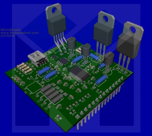
After some fast placement (which must be improved on highly) all the parts seem to fit. No traces yet, just placement by ratlines. First thing to do is to get all the part packages right, especially the capacitors need to be sourced first to know for certain which package is the right one. Also for the resistors i need to know the tolerances and which side (0.5w or other). Microblocks. Build with logic. |
||||
| matherp Guru Joined: 11/12/2012 Location: United KingdomPosts: 11608 |
The easiest way to check your schematic is to compare the netlist. I attach then netlist of my original. 2016-04-08_071631_netlist.zip The 1 ohm resistors need to be 1W, the backlight dropper 0.5W, all others can be 0.25W or greater. Tolerance doesn't matter too much as inaccuracies can be tuned out in software. The zener is probably not needed it is just there to protect the uP - I used 5V1. I strongly recommend having the 7805 and the LT3080 on the same edge so they can be connected to the main heatsink. The 3.3V reg can be separate but should still have a local heatsink. The output of the IN169 is set by the combination of the parallel shunt resistors and the gain resistor. You can use 2x 1ohm + 2x 10K or 4 x 1ohm + 1x 10K. The latter is preferred. My layout includes pads for both options. |
||||
| bigmik Guru Joined: 20/06/2011 Location: AustraliaPosts: 2981 |
Gday microblocks, all, That looks good as a start but don't forget you will need at least 4 mounting holes.. Mick Mick's uMite Stuff can be found >>> HERE (Kindly hosted by Dontronics) <<< |
||||
| MicroBlocks Guru Joined: 12/05/2012 Location: ThailandPosts: 2209 |
Hi Mick, I have a 'system' for bread boarding in development so i use a 50x50mm grid for mounting. like this (shown is a carrier for prototyping with my other modules) 
It also has holes in the center and two on the side to allow for other design to at least have 3-4 mounting holes. Microblocks. Build with logic. |
||||
| isochronic Guru Joined: 21/01/2012 Location: AustraliaPosts: 689 |
If only 3.3 v is needed - this might be the go - a press release I know but... http://www.microchip.com/wwwproducts/en/MIC45404#utm_source=Press_Release&utm_medium=Press_Release&utm_term=FY16Q4&utm_c ontent=AIPD&utm_campaign=Press_Release |
||||
| paceman Guru Joined: 07/10/2011 Location: AustraliaPosts: 1329 |
Just the internal one on U1, op-amp out to transistor base - no consequence to your design at all. Greg |
||||
| MicroBlocks Guru Joined: 12/05/2012 Location: ThailandPosts: 2209 |
Thanks Matherp, i will use the netlist to check it. And having the right wattage for the resistors is great to make the right footprints. Chronic, that is one mighty interesting chip. More food for thought. Thanks. Microblocks. Build with logic. |
||||
| matherp Guru Joined: 11/12/2012 Location: United KingdomPosts: 11608 |
Here as promised are the basic steps for calibrating the power supply. To do this you need a decent quality multimeter and a 10ohm 25W power resistor Connect the resistor across the output Connect the supply voltage and set the output voltage to 5V and the output current to 1A Measure the voltage drop across the protection diode D3 and set this in line const diode=0.730 'measured drop on input diode to calibrate input voltage
Rerun the program and then change line const VIN_CAL=10.0 'set to calibrate input voltage measurement
until the displayed input voltage exactly matches the input voltage measured with your multimeter Now we can calibrate the displayed output voltage. leaving the power resistor in place and the output switched on change line const VOUT_CAL=9.94 'set to calibrate output voltage measurement
until the voltage measured across the power resistor is the same as the displayed voltage. Don't worry if this doesn't match the set voltage, we will deal with that in a later step. Now do the same for the measured output current. Put the multimeter in series with the power resistor on a range that can cope with at least 1A Change this line const IIN_CAL=0.4113 'Set to calibrate current measurement
until the measured current exactly matches the displayed output current. Again don't worry about the set current. Now we need to set the dropout voltage. Set the value in this line to zero const dropout=3.0 'excess of input voltage over output for control
set the output voltage to be the same as the input voltage (make sure that you are using an input of 12V or less to match the power resistor) and measure the actual output voltage. Set the dropout voltage parameter to match. The code has an iterative mechanisms that tries to adjust the output voltage and current to the measured values but we want them to be as exact as possible without adjustment Comment out the following lines: if abs(SetAmps-IIN)>0.001 and timer>500 then
AmpPwm=AmpPwm*SetAmps/IIN if AmpPwm>100 then AmpPwm=100 if AmpPwm< 0 then AmpPwm=0 pwm 1,10000,voltpwm,amppwm endif if abs(SetVolts-vout)> 33.3/4096 and timer>500 then
Voltpwm=voltpwm*SetVolts/vout if voltpwm>100 then voltpwm=100 if voltPwm< 0 then voltPwm=0 pwm 1,10000,voltpwm,amppwm endif Now set the output voltage to 5V and the current to 1A Adjust this line const VOLT_PWM_CAL=3.07 ' set to calibrate PWM voltage control
until the measure output voltage is as close as possible to the set voltage Set the current to 0.25A. Adjust this line const AMP_PWM_CAL=74.43 ' set to calibrate PWM current control
until the measured output current matches the set current. Finally, uncomment the iteration code. Run the power supply at a range of voltages and currents with different loads to check all is well. Note: in my prototype I am using C17 = 100uF 25V, R35=1K. C17 adjusts the speed that the supply responds to changes in load. Big value = slow but low ripple, small value = fast but more ripple. Resistors R28 and R49 set the gain of the current shunt amplifier and the shunt resistors used generate the voltage drop. We need to limit the amplifier output to be in the range of the Micromite ADC. Use 2* 10K + 2 * 1ohm or 1 * 10K + 4 * 1 ohm (preferred). Either of these give 2.5V output for 1A current |
||||
| Emady Newbie Joined: 02/02/2016 Location: United KingdomPosts: 23 |
Hi all, What a nice project matherp, just what I was looking for, thanks. Could you please let me know what voltage should Vin be? To MicroBlocks, you schematic is very good easy to read, I think U6 has the + and - reversed. I am gathering parts to start building this PSU. Regards, Elia |
||||
| matherp Guru Joined: 11/12/2012 Location: United KingdomPosts: 11608 |
My concept was to use an old laptop power brick - this would give an output range of around 0-15v. The main limitation is cooling the LT3080. Calculate the heat output for your worst case scenario (1V @ 1AMP off 24V supply = 23W!!!) and size the heatsink accordingly. 1W/degC is about as big as you can use without the die to case conductivity of the LT3080 being the limiting issue. |
||||
| MicroBlocks Guru Joined: 12/05/2012 Location: ThailandPosts: 2209 |
Thanks for spotting that! The LM334Z is available in different packages and that mixed up the pin numbers. I tried to compare everything with the original schematic and with the pcb traces. Once build i surely would have wondered why it didn't work.
@Matherp, Thanks for the writeup. That will help a lot. Microblocks. Build with logic. |
||||
| The Back Shed's forum code is written, and hosted, in Australia. | © JAQ Software 2026 |
