
|
|
Forum Index : Microcontroller and PC projects : Circuit diagram
| Author | Message | ||||
lew247 Guru Joined: 23/12/2015 Location: United KingdomPosts: 1709 |
2016-03-09_145026_Weather2.pdf Can someone (or more than one person) check the circuiit diagram and see if I have made any stupid errors? The main thing I need checked is the circuit around Q1 I decided to power the HC-12 433M Mhz transceiver module from a pin on the Micromite via a transistor I did this because being battery operated it will cut down on the current consumption as it can be powered up just before it needs to send a data burst and then powered down afterwards Is this a good idea or a bad idea? Attached is the modified circuit diagram Thanks to microblocks for helping me get it much neater and tidier than I could ever do Also - should I have the DS18B20 mounted ON the board, or have it as a header so it can be mounted elsewhere in the outdoor unit not near any possible heat source? 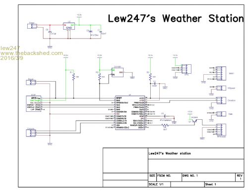
The picture's a bit small so it's attached as a pdf 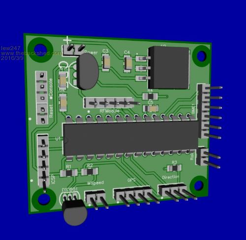
2016-03-09_144709_Weather2.zip |
||||
| lew247 Guru Joined: 23/12/2015 Location: United KingdomPosts: 1709 |
Also Can Someone please PLEASE check the TX and RX pins for the console COM1 to RF module pinouts and COM2 to GPS pinout on the circuit please I need someone to check my diagram and make certain the tx and rx tracks are in the correct place Please Thank you Lew 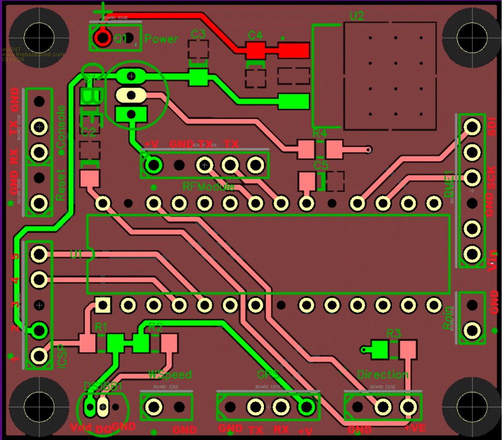
|
||||
| lew247 Guru Joined: 23/12/2015 Location: United KingdomPosts: 1709 |
Update: I've decided on the final circuit for the outdoor unit: Thanks to microblocks for making the circuit so neat and tidy, I could never have done that myself, I had wired crossing all over the place. The outdoor unit will not comprise of: Micromite GPS unit - for setting the clock on the inside unit, and also in case the outdoor unit gets stolen it will transmit it's location. BME280 Temp, Humidity and Pressure sensor DS18B20 for Temp as it's more accurate than the BME280 HC-12 Serial tx/rx 433 Mhz transceiver module Wind, Speed, and Direction sensors Console header ICSP header Reset header and 1A 3.3V regulator Battery monitoring circuit, as the battery is a 5V solar charged battery, it will measure the voltage and send it to the indoor unit so I can keep an eye on the battery and make sure it's charging correctly and doesn't get too low. Both the HC-12 and the battery monitor is powered via the micromite to cut down on current consumption, they will only be powered on when needed. Circuit below and the Diptrace ciruit is attached as well if anyone wants to see it. As to the code for the outdoor unit, I have all the various sensors working perfectly now, all I have to do is combine the various codes into one program and test it, which I can't do till I get a unit made up so I can power up all the modules at once. I used a micromite+ while I was writing the code and checking it worked, but when you add all the modules the 3.3V regulator on the micromite+ isn't able to handle the current (don't ask me how I know..... yes I damaged mine!!!) I believe its only a 250mA regulator and the unit when all modules are powered needs a little more than that but well under 1A 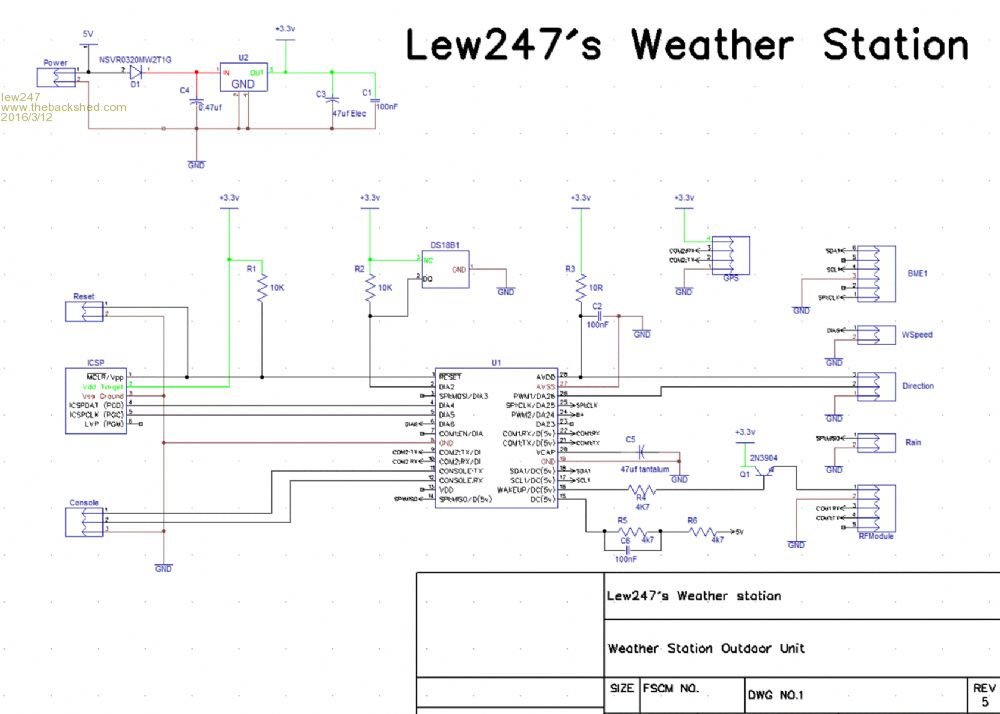
2016-03-12_133740_Weather5.zip |
||||
bigmik Guru Joined: 20/06/2011 Location: AustraliaPosts: 2981 |
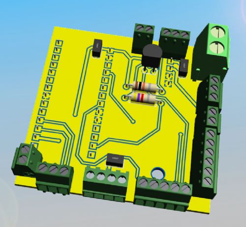
Hi Lew, MB, All, I had done a plug in board to suit a MuP and only needed to add the text overlays. But what has actually changed in your new schematic? And can you please upload a new hi-res version? I am not sure whether it is best as a plug in or as a standalone as per MB's board.. There is a problem with MB's if you want to use the screw terminals as these are about 6mm deep so some would interfere with some other components (esp. the right hand connectors, they would hit the pic chip.) They are, however perfect for pin header pins. For what it is worth and for the point of discussion I have attached the MuP-Weather 3D pics here. These are using 2.54mm pitch screw jacks for all except the Power IN which uses 5.08mm. Regards, Mick 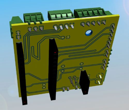
Mick's uMite Stuff can be found >>> HERE (Kindly hosted by Dontronics) <<< |
||||
| bigmik Guru Joined: 20/06/2011 Location: AustraliaPosts: 2981 |
Hi Lew, MB, All, Note the 3D jacks are close but not identical to the ones I actually have (the images I got for the 3D have plastic location pins mine do not) hence they look a little strange in the views. MuP-Weather is 49.5mm x 49.5mm (can layout 4 to a panel for manufacture) and plugs into MuP via the 3 female headers on the underside. The board is offset to allow access to the ICSP and CONSOLE headers on MuP, although there is a console screw jack as well.. The board can be smaller if we wish to go down this path as ICSP header can be added to MuP-Weather and we dont need access to MuP's console.. Anyway, Personally I am leaning towards MB's all-in-one board with some adjustments to fit screw terminals Regards, Mick Mick's uMite Stuff can be found >>> HERE (Kindly hosted by Dontronics) <<< |
||||
| HankR Senior Member Joined: 02/01/2015 Location: United StatesPosts: 209 |
For serious measurements, off board to go to a proper vented solar shield. Easy enough to connect a cable to the existing onboard pads, but how about parallel pads spaced for a two pin header so it's an option to do it either way? Still time for that mod? These collaborative efforts move along so rapidly. |
||||
| lew247 Guru Joined: 23/12/2015 Location: United KingdomPosts: 1709 |
I cannot figure out how to get a high res picture of it online The diptrace zip will show it best The mods as far as I can remember from what you saw last are battery monitoring, +and gnd of the monitoring circuit is supplied by the micromite to lower power consumption, a diode in the power trace going to the voltage rectifier - I've been known to connect power the wrong way in the past so I assume others might The HC-12 is powered by a transistor from the micromite again to lower consumption I think that's about it. I agree for a "one off" a seperate all in one board would be best but if anyone has a MuP available a standoff board would be ideal for this. |
||||
| lew247 Guru Joined: 23/12/2015 Location: United KingdomPosts: 1709 |
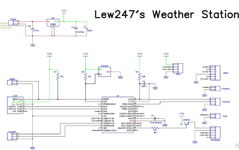
Figured it out :) I picked the NSVR0320MW2T1G for the diode because it only has a 0.3VF and is ideal for this purpose. Hi res picture  |
||||
| lew247 Guru Joined: 23/12/2015 Location: United KingdomPosts: 1709 |
Thinking about it the only thing that could improve it is the DS18B20 being mounted off the board, but thats easy enough as it is, although a 3 pin header would probably be a little neater. The board as it was the last time Microblocks did it was 50 X 44 but it doesn't actually have to be that small if it's an all in one unit. a little bigger won't hurt at all I did try routing it myself earlier but had to give up after 4 hours on it. |
||||
| MicroBlocks Guru Joined: 12/05/2012 Location: ThailandPosts: 2209 |
Hi Lew, The size can be a bit smaller or larger then 50x50mm. Maybe a good reason for size is how to mount it. If you have a case that you want to use maybe look at how to mount the pcb so that screw holes can be placed correctly. It seems the schematic is pretty good now and most modifications done. Maybe some more testing of for instance the diode or switching transistor to make sure not a slight modification is needed. When making a PCB you get not many changes to get it right, so getting close to perfect is best. Currently in the middle of move to another city (moving lots of boxes....) I will come back to it on Monday. Also try to find which screw terminal you want to use, so that i can use the right footprints and dimension for placement. Microblocks. Build with logic. |
||||
| lew247 Guru Joined: 23/12/2015 Location: United KingdomPosts: 1709 |
Simple answer is I've no idea I have no experience with screw terminal sizes< I have asked WhiteWizzard for suggestions or if anyone else wants to suggest one It is very low voltage (5V) and very low current (less than 1A) so they can be pretty small As to the design I have no means of testing the circuit as I have damaged the voltage regulator on my micromite+ and it was the only micromite I have. I'm pretty certain the circuit will work as it it, if anyone can look at it and check I'd be more than grateful. I spent all of today trying to replicate microblocks work but I'm really hopeless when it comes to Diptrace. I cannot figure out how to make a new component for the NSVR0320MW2T1G diode It's an SOD-323 sized component The best I have managed to get is a board 90mm X 80mm but I need to move 2 traces sllghtly to the left but I have no idea how to get at the bottom of the board to move the traces (it was done with the autorouter) Made one FINAL change tonight Added a header for a LUX/UV index sensor and the DA18B20 is on a header so the sensor can be placed where its needed. 
|
||||
| MicroBlocks Guru Joined: 12/05/2012 Location: ThailandPosts: 2209 |
I was looking at the voltage divider that is connected to pin 15 of the PIC. Here two 4k7 resistors are used. The voltage can be read by lowering pin 15 and waiting a short period to allow the capacitor to charge. It is being use to detect if power is disconnected and switched over to battery. Would it not be easier to use 1M resistors and instead of connecting it to pin 15 connect it to GND? Also drop the capacitor as it is not adding anything. It would then consume a few microamps. Nothing to worry about i think. Or do i miss something? Microblocks. Build with logic. |
||||
| WhiteWizzard Guru Joined: 05/04/2013 Location: United KingdomPosts: 2991 |
@MicoBlocks The PIC requires a certain input current to read analogue 'accurately'; and for this reason it is better to use 'lower' value resistors and only switch them in when required. This method also prevents excess draw on certain battery chemistries that would otherwise result in shorter battery life. In the early days of me designing ultra low power 'stuff' I did exactly what you said (470K/1M/4M7) and wondered why my circuits mis-behaved. The 'switching' technique does require a little more hardware (and a bit extra software) - but I find it works 100% reliably. |
||||
| MicroBlocks Guru Joined: 12/05/2012 Location: ThailandPosts: 2209 |
@WW, Thanks for the explanation. I used the 1M resistor dividers with Atmel chips and that worked ok. I would never have figured that out reading the PIC32 datasheets. Microblocks. Build with logic. |
||||
| JohnS Guru Joined: 18/11/2011 Location: United KingdomPosts: 4344 |
Is the Atmel not in essence an RC network (thus a time constant) and successive approximation? I thought so and that the PIC is too. So, big R means you have to wait longer to get an accurate reading. Am I missing something here? Please explain what :) John |
||||
| WhiteWizzard Guru Joined: 05/04/2013 Location: United KingdomPosts: 2991 |
In the MicroChip datasheet; the 'recommended' Impedance of Analogue Voltage Source = 5K. The way I have always looked at this is that this equates to requiring a 'minimum' current flow - and this corresponds with the results I saw (pre uM days!). Not had enough to do with analogue on a uM; but I do remember this conversation coming up before on TBS. |
||||
| matherp Guru Joined: 11/12/2012 Location: United KingdomPosts: 11604 |
The model of the ADC input is as below: 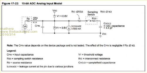
You will note there is a +/- 500nA leakage and the pin capacitance to take into account at all times. When the sampling time is started the input has to charge the 4.4pF capacitor. The sampling time can be set in software but in the Micromite firmware is fixed at a "normal" level. Page 275 of the PIC32MX170 datasheet gives a recommended source impedance of 5K. |
||||
| JohnS Guru Joined: 18/11/2011 Location: United KingdomPosts: 4344 |
Thanks, guys! 5K does rather rule out 1M. By implication the Atmel (whichever chip) must not have a similar figure. John |
||||
| lew247 Guru Joined: 23/12/2015 Location: United KingdomPosts: 1709 |
Battery backup circuit I added this as a "just in case". The kids round here stole my last weather station, I know it stayed locally but I had no way to track or find it. My reasoning for the battery backup - runs off 2 X AA(R6) 1.5V cells The 2nd diode blocks the battery from being charged by the 5v circuit, if the external battery - in my case a Solar charged 5V cell is disconnected from the circuit, then the voltage will drop, the Micromite will detect this lower voltage and get the Micromite to transmit it's location from the GPS receiver every say 30 seconds. (time can be adjusted) This way - driving round or walking round the neighbourhood with a HC-12 connected to the com port on a laptop the location of the outdoor unit can be traced - ie drive or walk round until you get anything from the HC-12 433Mhz tr/rx, then once its found the terminal program will show the location of the unit - as the exact location will be transmitted allowing it to be recovered. The circuit could also sound a mini sounder/siren using the same circuit if needed, which would probably stop anyone who was stealing the unit - they'd probably drop the unit with shock! I know in 99% of the cases it's overkill and not needed but I wanted it in "just in case". Oh I've also added a LUX sensor to the circuit diagram (not shown below) 
|
||||
| HankR Senior Member Joined: 02/01/2015 Location: United StatesPosts: 209 |
Actually Atmel 8 bit uPs have the same system; the on-chip circuit values may even be identical. Haven't checked the Atmel 32 bit uP A/Ds, but I would guess those A/D inputs are similar with the same attendant limitations on driving current from the measured source. |
||||
| The Back Shed's forum code is written, and hosted, in Australia. | © JAQ Software 2026 |
