
|
|
Forum Index : Microcontroller and PC projects : uMite mx170 44 pin & USB/programmer DIP40
| Author | Message | ||||
| HankR Senior Member Joined: 02/01/2015 Location: United StatesPosts: 209 |
The FRAM would be excellent, allowing for data logging. I think that would be a very valuable addition. |
||||
| MicroBlocks Guru Joined: 12/05/2012 Location: ThailandPosts: 2209 |
Any remarks what i should do with the 32Khz and INT/SQW output pins? I am considering placing a solder bridge between the INT/SQW out pin from the RTC to pin 42. You would then be able to use it as an interrupt or for counting. The 32Khz is way to fast to use as an interrupt so i probably want to keep that one unconnected. Is there a consensus to set the address for an FRAM chip. I considering using the MB85RC256V which has three pins to sets its I2C address. [code] � Device Type Code (4 bits) The upper 4 bits of the device address word are a device type code that identifies the device type, and are fixed at �1010� for the MB85RC256V. � Device Address Code (3 bits) Following the device type code, the 3 bits of the device address code are input in order of A2, A1, and A0. The device address code identifies one device from up to eight devices connected to the bus. Each MB85RC256V is given a unique 3 bits code on the device address pin (external hardware pin A2, A1, and A0). The slave only responds if the received device address code is equal to this unique 3 bits code. [/code] I am also considering using a (super)cap instead of a battery as probably power interruptions are relatively short. Reading about that now to see if it offers enough backup time. I seem to recall that someone else used an FRAM before (was that Grogster?) and using the same address would be at least staying compatible with that. Or should i add more solder bridges to set the address, which is maybe the best way to go. Opinions please. :) Microblocks. Build with logic. |
||||
| isochronic Guru Joined: 21/01/2012 Location: AustraliaPosts: 689 |
It would be good to use the 32kHz from the maxim rtc as input to the secondary oscillator pin on the pic. The idea is, on startup, the pic loads current time date etc from the maxim into the pic rtcc, then uses the accurate 32khz to maintain the time data. Haven't tried it yet, I am using a ds3234 plugin which is the spi version. I have found the ds3234 good, I had problems with noise pickup in cables etc but when everything is nailed down it is very reliable (so far). |
||||
| MicroBlocks Guru Joined: 12/05/2012 Location: ThailandPosts: 2209 |
The secondary oscillator pin on the PIC is pin 34 and that pin is currently hardwired as a console RX. My thinking is to use the INT/SQW (1Hz) from the RTC is that at least you can count the number of seconds since the last time you read the info from the RTC and have an accurate clock that way. Microblocks. Build with logic. |
||||
| HankR Senior Member Joined: 02/01/2015 Location: United StatesPosts: 209 |
At least one or two solder bridges, please. That sounds good. |
||||
| isochronic Guru Joined: 21/01/2012 Location: AustraliaPosts: 689 |
Forgot about the console (!)  Need sleep... Need sleep...
|
||||
| MicroBlocks Guru Joined: 12/05/2012 Location: ThailandPosts: 2209 |
It seems Cypress has higher capacity FRAM available. So it will also be possible to use a FM24V10 (128Kx8bit) or FM24W256 (32Kx8bit). They share the same footprint as the Fujitsu chip. This can also be handy for certain applications where a unique ID is required. [code] Unique Serial Number (FM24VN10 only) The FM24VN10 device also incorporates a read-only 8-byte serial number. It can be used to uniquely identify a pc board or system. The serial number includes a 40-bit unique number, an 8-bit CRC, and a 16-bit number that can be defined upon request by the customer. If a customer-specific number is not requested, the 16-bit Customer Identifier is 0000h. The 8 bytes of data are accessed via a slave address sequence similar to the Device ID. [/code] Microblocks. Build with logic. |
||||
| MicroBlocks Guru Joined: 12/05/2012 Location: ThailandPosts: 2209 |
I have added the two parts to the schematic. Now squeezing it onto the pcb. 
RTC (DS3231MZ/DS3232MZ) The DS3232MZ has some extra RAM on board. 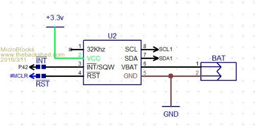
FRAM: 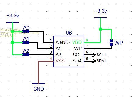
I also put two pull-up resistors on the board, i am thinking about a solder bridge for them. Would that be necessary when adding external I2C parts? Microblocks. Build with logic. |
||||
bigmik Guru Joined: 20/06/2011 Location: AustraliaPosts: 2981 |
GDay MB, ALL, Hey!! I didn't know that there was a DS3231MZ variety, That is available for about $9each ($Aus) from Element14.. I have just about given up on the DS3232MZ as it was too costly but $9AU for the DS3231MZ is getting close and that is for 1off (10off is a little over $8Au).. Might have to source some of them. Regards, Mick PS. I had an inquiry for some SMD-BP170 Boards/kits a few weeks ago but I read it at work (on a work PC) and at the time I was out of stock of the SSOP MX170. I have lost the email.. If that person is a member of TBS and is still interested please PM or email me again. Regards, Mick Mick's uMite Stuff can be found >>> HERE (Kindly hosted by Dontronics) <<< |
||||
| MicroBlocks Guru Joined: 12/05/2012 Location: ThailandPosts: 2209 |
Here are the PDF's for the DS3231 and the DS3232. Oops they are too large. I have to find the links again. moment..... Here they are: DS3231M DS3232M Microblocks. Build with logic. |
||||
| MicroBlocks Guru Joined: 12/05/2012 Location: ThailandPosts: 2209 |
Well that was a fight. :) I did get everything on the PCB although i even had to customize some capacitor footprints to make them a tiny bit smaller but still the right size for the components i have. Thank you digital calipers. :) 2016-03-12_135715_DipTrace_Schematic_-_UMX170-44.pdf Top: 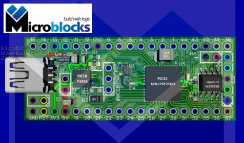
Larger image: Top Bottom: 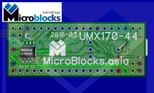
Larger image: bottom Microblocks. Build with logic. |
||||
| bigmik Guru Joined: 20/06/2011 Location: AustraliaPosts: 2981 |
Jean, That is extraordinary... I am struggling to believe what you have finally come up with.. WELL DONE!! 
But seriously can you squeeze in a simple i7 CPU in all that spare space on the underside?? 
This is a MUST have IMHO. Regards, Mick Mick's uMite Stuff can be found >>> HERE (Kindly hosted by Dontronics) <<< |
||||
| MicroBlocks Guru Joined: 12/05/2012 Location: ThailandPosts: 2209 |
Thanks Mick! I found out that I2C EEPROM's also have the same pin layout so that would then also be an option. I added two header pins. 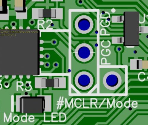
This will allow to put the pic16 into programmer mode easier. Just place a jumper on #MCLR and Mode. The Mode led will then indicate programmer mode. The second is a 3v3 header to make all the needed pins for the pic16f1455 icsp available. I tried to fit in a 5 pin icsp header but that is with only two layers very difficult. For normal use you would probably never need them, but for hackability a must. 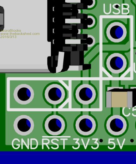
Also renamed the jumper for selecting USB power from J1 to USB. This 'jumper' actually offers some extra possibilities. It could be a place to measure current (high side shunt resistor). Or instead of a jumper a PTC can be used, or a diode. Instead of providing space for all of that, the single jumper gives you these choices. I also put all the pin numbers on the bottom side to make finding them easier. The RST pin is not directly connected to the PIC32 but lowers the voltage on a pin of a supervisory chip. This results is a nice clean reset signal to the PIC32 of about 250ms. Resetting the PIC32 will not break the USB connection, so staying connected is guaranteed. This will allow for applications that log to a USB port to be uninterrupted in cases a reset is necessary (watchdog or external condition). It also makes it easier to reset the MMBasic as after a reset you can send a string of '!' to do a complete reset (wiping basic program and variables). 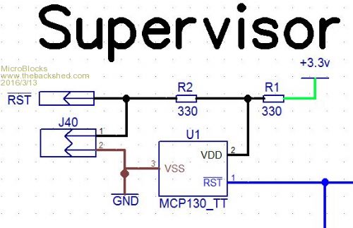
Microblocks. Build with logic. |
||||
| MicroBlocks Guru Joined: 12/05/2012 Location: ThailandPosts: 2209 |
Currently changing the layout and removing/replacing some parts to allow for a better voltage regulator performance (SOT-89). Also changed the supervisory circuit to a standard use to allow connection of a pickit3 to the PIC32 for direct programming & debugging. Still struggling to add pins for the console (they are now exclusively connected to the pic16f1455 for USB-Serial). The TX could be used to wakeup the pic so i will try to at least make that one available. Microblocks. Build with logic. |
||||
| MicroBlocks Guru Joined: 12/05/2012 Location: ThailandPosts: 2209 |
Well 17 days later! and i have finally reached a point that i am satisfied with the design. I considered all the feedback and now used a much more beefier voltage regulator that can deliver max 500ma. Also the pins for the console are accessible and right next to the USB port to keep the connection to a terminal on a single side. The best thing however (i think) is the addition of a flash chip footprint so that a winbond or compatible chip can be added. This will give a large capacity of storage. Peter already made a Cfunction to use this chip, so it will be ready to go. My feeling is that this design will be great to use for when you want to log information. The RTC (DS3231/2) for timekeeping, up to 8MB flash and to top it of on the bottom side you can add two serial eproms or even better FRAM. Another 'feature' is that it has most of the pins grouped, like I2C, SPI, PWM, SERIAL so that connecting other parts will be extremely easy. It also shares the same layout as the DIP28 version. It would then be possible to upgrade a UMX170-28 module with a UMX170-44 module. I should change the topic into DIP38 as it is a little shorter then a DIP40. This to conform with my other parts that are max 50mm. This one is 19.8x49.85mm which panelizes easy into a 10x10cm. 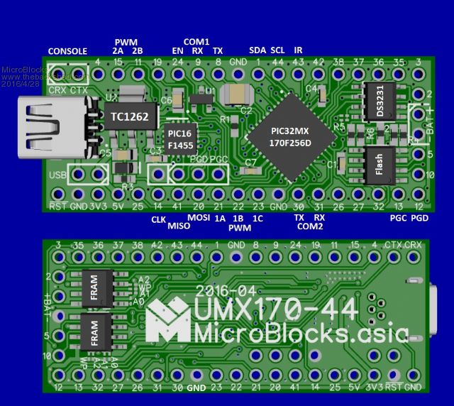
One of the things i am still considering is to drop one FRAM footprint and add a 9-DOF sensor. What do you think? Microblocks. Build with logic. |
||||
| Phil23 Guru Joined: 27/03/2016 Location: AustraliaPosts: 1667 |
Just newbie feedback. Love to have some like that to play with. But,some sittings I press the reset button a LOT.... How about one like this? 
That ones on a HC-05 Bluetooth module Cheers Phil |
||||
| MicroBlocks Guru Joined: 12/05/2012 Location: ThailandPosts: 2209 |
The reset pin is right next to a GND pin, so just add a header. If you plug this in a breadboard, push a momentary switch between the GND power lane and the RST pin. If you use a terminal to program it, press CTRL+R and the PIC16F1455 that acts as a USB-Serial (also programmer) will pull the #MCLR pin low and resets the PIC32. The choice on what to add and what to leave out is always a difficult one. The same goes for adding a LED to indicate power. Maybe nice to have but if you have a USB connection then that is a good indication that power is available. For use with a battery a LED uses more power then the PIC32 and PIC16 together. The list of things to add and leave out goes on. The USB header (to enable power from USB) is also such a case. Many want a diode to protect against connecting USB power and external power. Others want a PTC to protect against large currents (which the voltage regulator already does) etc. The USB header leaves that choice open. Want a diode, then add it. Rather have a PTC, well just add it. :) I think a jumper is the easiest solution and still offers those possibilities. If used as a uMite then a reset is hardly necessary. When programming you would more often use CTRL+C to stop a running program and give the command NEW to erase everything or the command RUN to start it again. I find myself almost never using the reset switch. In other cases (arduino/ direct PIC) it is used more often. Above is my way of thinking to make it the most versatile and useful. Microblocks. Build with logic. |
||||
| Bill7300 Senior Member Joined: 05/08/2014 Location: AustraliaPosts: 159 |
Getting back to your other question Jean, I would certainly find use for a 9 DOF sensor in lieu of one FRAM. Bill Bill |
||||
| matherp Guru Joined: 11/12/2012 Location: United KingdomPosts: 11604 |
Having played quite a bit with the various DOF chips I'd recommend a 6-DOF (MPU-6150). The 9-DOF MPU-9250 is actually two chips in the package with the magnetometer separate from the accelerometers and it is a very poor magnetometer compared with the HMC5883. To get reliable magnetometer readings the chip needs to be kept away, to the extent possible, from any and all electrical wiring and magnetic influence. This is easier to achieve if it is separate from the main PCB. JMHO |
||||
| MicroBlocks Guru Joined: 12/05/2012 Location: ThailandPosts: 2209 |
Good point. How would a MPU-6150 perform directly on the PCB. Is it just as sensitive to the electric signals. As that area is pretty full and has traces for I2C and SPI i suspect it will generate some 'noise' that could be detrimental. Then again these things are also used in drones with lots of motors and other signals. I did not find good examples or reading material that covers this subject so i have to go on peoples experiences. Microblocks. Build with logic. |
||||
| The Back Shed's forum code is written, and hosted, in Australia. | © JAQ Software 2026 |
