
|
|
Forum Index : Microcontroller and PC projects : uM2(+): Wifi replaces USB for console?
| Author | Message | ||||
| JohnS Guru Joined: 18/11/2011 Location: United KingdomPosts: 4352 |
+1 on power, they need more than you'd think (well, than I did till I tried a better PSU) John |
||||
| Phil23 Guru Joined: 27/03/2016 Location: AustraliaPosts: 1667 |
No way can I get ESP_Basic_Flasher.exe to not error. Even tried moving the CP2102 to a different com port address. As far as the other programmer is concerned, it now runs & completes in a few seconds. I'd overlooked pulling GPIO0 low, but I've also taken3.3v power from an Ardruino board now as well. The programmer returned this in it's log:- 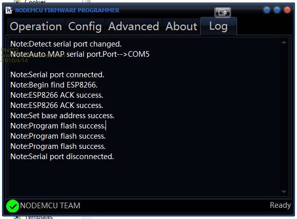
But on reset I don't seem to see an available network. The AI-Thinker AP is no longer visible. Presuming CH_PD is still meant to be held high & GPIO0 is no longer pulled low. A small step though...... I hope. |
||||
| matherp Guru Joined: 11/12/2012 Location: United KingdomPosts: 11645 |
3.3V from an Arduino? |
||||
| Phil23 Guru Joined: 27/03/2016 Location: AustraliaPosts: 1667 |
Presuming it's a valid supply. 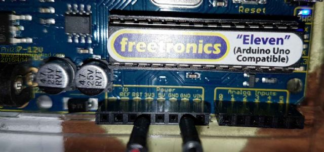
Log from the programmer seems ok? |
||||
| JohnS Guru Joined: 18/11/2011 Location: United KingdomPosts: 4352 |
Is that because you've put code into it that does not make one visible? John |
||||
| Phil23 Guru Joined: 27/03/2016 Location: AustraliaPosts: 1667 |
I don't think so. The Binaries I used are these as per the first post in this thread. |
||||
| matherp Guru Joined: 11/12/2012 Location: United KingdomPosts: 11645 |
Is your PCB blue or Black? |
||||
| Phil23 Guru Joined: 27/03/2016 Location: AustraliaPosts: 1667 |
It's a black board. labelled AI-Cloud. Not id's printed on the pinouts. On reboot I'm not getting any of the Led indicators mentioned. |
||||
| matherp Guru Joined: 11/12/2012 Location: United KingdomPosts: 11645 |
That is the same one I'm using so that shouldn't be an issue. Are you definitely loading blank.bin to 0xFE000? Have you managed to flash ESPBasic? Until you can do that reliably I would suspect there is still something wrong with the flashing process. It should be completely reliable as long as you use the reset trick and the wiring is as per the ESPBasic site |
||||
| Phil23 Guru Joined: 27/03/2016 Location: AustraliaPosts: 1667 |
|
||||
| robert.rozee Guru Joined: 31/12/2012 Location: New ZealandPosts: 2541 |
no, it is not a valid supply, in the sense that it is produced by the arduino's USB to serial bridge chip. a maximum of only 50mA or so can be drawn. might i suggest a 3x AA battery holder - one of the nice ones available on ebay with a built-in switch: http://www.ebay.com/itm/381208208080 along with a 3-terminal LDO regulator like the LM1117-3v3 in TO-220 package: http://www.ebay.com/itm/221897784452 assemble LDO regulator on a piece of veroboard, along with filtering capacitors (0.1uF ceramic + 10uF electro on input terminal, 0.1uF ceramic and 100uF electro on output terminal), and a high-brightness LED + series resistor across the 3v3 output to show that the battery is switched on. high-brightness LEDs will usually give a fairly bright indication with 1mA or less of current, so won't excessively drain your batteries. this will give you a good solid 3v3 supply, is isolated with no 50/60Hz hum, and should provide you with enough juice for at least 10 or so hours while you get things set up. cheers, rob :-) |
||||
| Phil23 Guru Joined: 27/03/2016 Location: AustraliaPosts: 1667 |
Was actually planning on doing that with a 4 Cell holder I have for the purpose. Primarily 4 cell as I have a large collection of Enneloops that I cycle in sets of 4. Was going to bit it both 3.3 & 5 volt rails. |
||||
| robert.rozee Guru Joined: 31/12/2012 Location: New ZealandPosts: 2541 |
Was actually planning on doing that with a 4 Cell holder I have for the purpose. Primarily 4 cell as I have a large collection of Enneloops that I cycle in sets of 4. Was going to bit it both 3.3 & 5 volt rails. with an external plug pack connected, the 3v3 rail from an arduino is still sourced from the USB to serial bridge and limited to 50mA or thereabouts. what voltage are eneloops? if they are like normal Ni-Mh cells, they will peak at about 1.4v when topped up and have a running voltage of about 1.2v, which will be perfect for regulating down to 3v3 with an LM1117-3v3. four eneloops may not be too great for getting the 5v rail, if indeed you need 5v; unregulated, they will be too high when fully charged (1.4 x 4 = 5.6v), and when not topped up will be too low (1.2 x 4 = 4.8v) to regulate down to 5v. cheers, rob :-) |
||||
| matherp Guru Joined: 11/12/2012 Location: United KingdomPosts: 11645 |
Phil23 One other issue. As I said in my original post if you have previously loaded ESP8266Basic you must use the erase flash facility in the ESP8266 loader before you can load different firmware |
||||
| Phil23 Guru Joined: 27/03/2016 Location: AustraliaPosts: 1667 |
Problem finally solved! Programmed & up & running. Most of my issues were related to inexperience in this general area, along with a few slip ups. Thought I'd list them for others who fall off the pearch. [Code] 1. Hold CH_PD high, (Got that one from the start). 2. Pull GPIO0 low, (One I missed initially). 3. Be aware of how good your 3.3 power supply is. (In hind sight both CP2102, & the one from the Ardruino board worked, but as others recommend, something more beefy would be better). 4. Know you flash size, I didn't, and had to make an assisted guess. 5. Basic Flash would not load unless reset pin is momentarily pulled low after the flashing process is started. 6. After EspFlasher is told to flash, also pull the reset low momentarily. 7. And finally, check that all the binaries are selected to be loaded. This was my final brick wall. Initially they were all checked, but at some point the 2nd & 3rd became unchecked & it was something I was overlooking, leading to all the hair tearing. [/code] 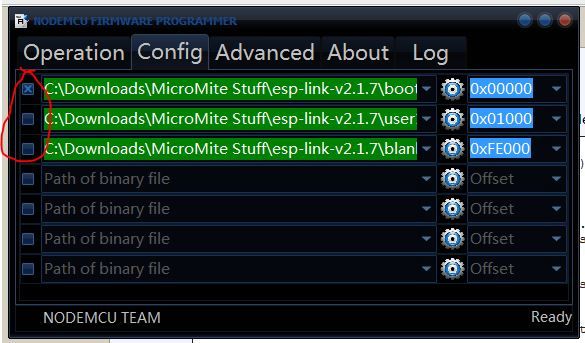
Thanks to all who have helped. Cheers. |
||||
lew247 Guru Joined: 23/12/2015 Location: United KingdomPosts: 1709 |
Using the picture below could anyone please confirm which pins go where when flashing the ESP8266? Also what is the program (ESP8266Flasher.exe) meant to say while flashing, and how long does it take? Do the tx pins go to rx on the flasher and vice versa? Finally could someone please confirm which pins go to the console pins on the Micromite? ie which pins goes to console tx and which goes to console rx? Thanks 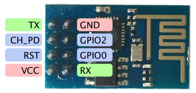
|
||||
| MikeO Senior Member Joined: 11/09/2011 Location: AustraliaPosts: 275 |
Lewis, You can use this diagram. You don't need the serial resistors. This is my setup, you have to have X set on the left hand side or it won't flash the files. See this link, scroll down to "Install via serial upload". 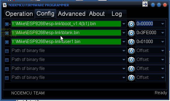
This should always work ,you don't need to set the baud rate, if it doesn't start and you have boot set then you have the TX/RX lines the wrong way round. Good luck Mike. Codenquilts |
||||
| lew247 Guru Joined: 23/12/2015 Location: United KingdomPosts: 1709 |
Thanks Mike I plan on using it on my outdoor weather board so I can program new code into it as and when needed, save me taking it down each time I want to try something new or add a new feature/clean up the code |
||||
| lew247 Guru Joined: 23/12/2015 Location: United KingdomPosts: 1709 |
I'm pretty sure it flashed correctly but I can't find it - there is no wifi network detected by my laptop or phone I was hoping to see this [code]esp-link creates a wifi access point with an SSID of the form ESP_012ABC (some modules use a different SSID form, such as ai-thinker-012ABC)[/code] no network other than my normal wireless router any ideas? This is what came up after flashing so I'm assuming it went right 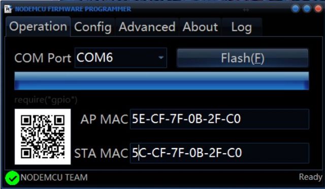
|
||||
| Phil23 Guru Joined: 27/03/2016 Location: AustraliaPosts: 1667 |
I went back to flashing with Esp Basic, then checked it was an available access point and that i could to it. Then flashed it with Esp Link and tried again. Did you disconnect GPIO0 and then reset it after the second flesh? Can understand your frustration, took me a few days to get it right. Cheers. Worst still it is simple peeve you get it right. |
||||
| The Back Shed's forum code is written, and hosted, in Australia. | © JAQ Software 2026 |
