
|
|
Forum Index : Microcontroller and PC projects : MM+, Explore 64 and Explore 100
| Author | Message | ||||
Grogster Admin Group Joined: 31/12/2012 Location: New ZealandPosts: 10005 |
On the E100 board, CON6 is connected directly to the console. I will try to get these ZIP file links up soon - I have had a dose of the flu, and have not been at my computer for the last few days.....  Smoke makes things work. When the smoke gets out, it stops! |
||||
| Grogster Admin Group Joined: 31/12/2012 Location: New ZealandPosts: 10005 |
OK, I have FINALLY got this done. ZIP file constructor's packs can be downloaded from my website. This link should always remain active, so will be current even if the downloads are updated. No guarantee though, but it SHOULD stay at that address as long as my website is alive..... Packs are available for both the E64 and the E100. Geoff has authorised me to release these publicly for anyone to use who wants to make their own boards etc. Both of these packs contain the Gerber files, 1200dpi GIF images of the board layers, BOM in GIF and ODS formats, and the original Sprint Layout 6 file for those of you using Sprint Layout(probably not many members here). The E64 package was available before today, but I have updated it to include more information and an ODS BOM file, so you can copy-and-paste part numbers to quickly link to what you need from the web. The old E64 download has been removed. If anyone sees anything obviously wrong in there somewhere, please let me know. Smoke makes things work. When the smoke gets out, it stops! |
||||
yahoo2 Guru Joined: 05/04/2011 Location: AustraliaPosts: 1166 |
I have to say I am a little bit pumped about the E100. Do you remember this! the Holden EFIJY 
photo: GM-holden built in 2005 with a touchscreen centre console and instrument bezel driven by 8 picaxe chips. I had been using big touchscreen consoles for gps guidance in machinery with wondoze 98 for about 5 years when this car was built, I remember thinking then, bring it on! I need some of that. I'm confused, no wait... maybe I'm not... |
||||
| Grogster Admin Group Joined: 31/12/2012 Location: New ZealandPosts: 10005 |
As a heads-up for TBS forum members, just to make you aware that the exciting new MicroMite+ Explore100 TFT Module that will be featured in SC soon is available to back-order now from either myself RICTECH LTD's MicroMite page(shipping from New Zealand), or from WhiteWizzard (MICROMITE.ORG shipping from UK). We are both offering the 4-layer unpopulated PCB at the same price (US$12 + postage); therefore, choose whoever is nearest to you to minimise your shipping costs, and also minimise delivery timescales. WhiteWizzard is also offering the PCB with just the SMD components soldered (and MMBasic pre-loaded) US$40; and I will be offering a Full kit of parts (with SMDs pre-soldered) US$75. I will not be offering the PCB with just the SMD fitted, only full kits. The full kit includes a PCB with the SMD fitted though. If you want a PCB with the SMD fitted, but NOT a full kit, then WhiteWizzard can help you there. No TFTs are included as there are many low-cost sources (on the likes of eBay) to meet specific individual requirements. I imagine this will be a very popular module once it is published in SC so to guarantee early delivery, please visit our websites if you're interested in obtaining a MicroMite+ Explore100. Smoke makes things work. When the smoke gets out, it stops! |
||||
f1fco Senior Member Joined: 18/03/2012 Location: FrancePosts: 155 |
hello to all, what kind of SDcard board to use for this beautifully PCB (I want to order one...) please a link on ebay for a 8 pins "ALT SD CARD" (it is the name of CON 10 on the schematics) thank you for answer Pierre, from Nimes, south of France 73s de F1FCO |
||||
| Grogster Admin Group Joined: 31/12/2012 Location: New ZealandPosts: 10005 |
Bonjour. There is no "Alt SD CARD" board. This connector(CON10) is for if you want an external SD card which is separate from the SD card that is included on the LCD. I have not designed such an SD card board, but I am thinking about it, cos you are not the only one to ask about this........ At this stage, if you want an external SD card, you have to design a carrier board for the SD card socket yourself. CON10 was more of an afterthought then anything else, as the plan was(and still is) to use the SD card socket which comes built-in to most LCD modules. It would not take long to whip up a board that would suit that pinout. Is anyone else interested in that? Au revoir. Smoke makes things work. When the smoke gets out, it stops! |
||||
| f1fco Senior Member Joined: 18/03/2012 Location: FrancePosts: 155 |
hello Graeme, thank you for your fast answer I am also interested by one SD card board to plug in CON 10 util to use the Explore 100 board without an LCD display thank you again for your work Pierre. 73s de F1FCO |
||||
jman Guru Joined: 12/06/2011 Location: New ZealandPosts: 711 |
Hi Why not just buy one these Ebay SD Card Board Jman |
||||
mikeb Senior Member Joined: 10/04/2016 Location: AustraliaPosts: 180 |
Only problem with any of these SD card modules is that they don't make the 'card detect' switch available at the connector, although it would be an easy matter to 'hack' the board to make it so. There are 10 kinds of people in the world. Those that understand binary and those that don't. |
||||
| f1fco Senior Member Joined: 18/03/2012 Location: FrancePosts: 155 |
thank you Jman for your link on ebay but this board as only 6 pins, not directly compatible with the 8 pins of CON 10 I wait for a "special" board from Grogster Pierre. 73s de F1FCO |
||||
| lew247 Guru Joined: 23/12/2015 Location: United KingdomPosts: 1709 |
Can anyone tell me is the RD pin on the display connected on this board and if so which pin is it connected to? Also does anyone have a diptrace layout for the "Click Board" that plugs into this please? |
||||
| matherp Guru Joined: 11/12/2012 Location: United KingdomPosts: 11682 |
Yes: 6 |
||||
| Grogster Admin Group Joined: 31/12/2012 Location: New ZealandPosts: 10005 |
...and R10 is a 10k pullup for this pin. F_CS is also connected on the 1B boards, allowing use of those neat SPI flash memory chips that our resident guru has already written Cfunctions/CSubs for. Normally this is an unpopulated footprint on the SSD1963 LCD boards, and the flash memory IC's CS line comes back to the main I/O connector on the "F_CS" pin. On the 1B E100 boards(which are the ones everyone will get), this is connected to pin-58(also the cathode of LED D2, which means that this LED will blink if the flash memory is accessed.) The 1A(prototype) PCB has "F_CS" pulled high permanently, and it is an interior layer that does it, so if you happen to have a 1A prototype board, you won't be able to - easily - use SPI memory on the LCD module. On the 1B's you can. [Quote=lew247]Also does anyone have a diptrace layout for the "Click Board" that plugs into this please? [/Quote] I can upload a ZIP file of Gerbers for the Click module footprint used on the E100 board if that would be of any help to you or others. You would have to be able to import Gerber files(274-X) and Excellon drill data to re-construct the footprint with silkscreen etc, and then you could save THAT in your own CAD software's file format. Smoke makes things work. When the smoke gets out, it stops! |
||||
| Phil23 Guru Joined: 27/03/2016 Location: AustraliaPosts: 1667 |
Grog....... Just had the knock on the front door...... Couple of E100's...... For those who haven't seen how Grog's sending them out, check this out. I think it's pretty cool. Thanks for the extra effort. 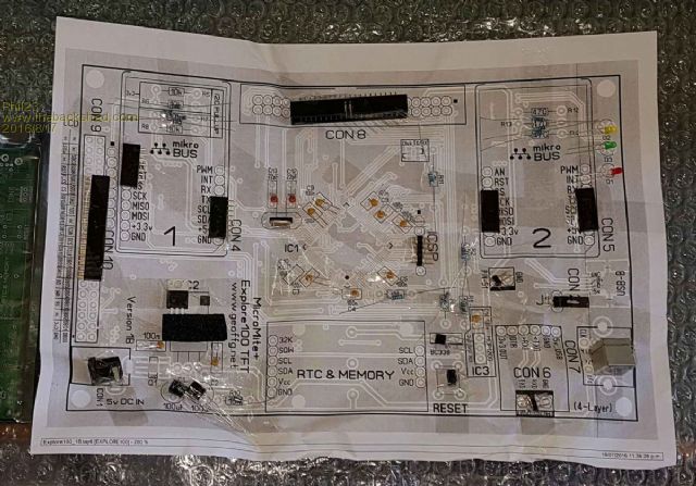
|
||||
| Zonker Guru Joined: 18/08/2012 Location: United StatesPosts: 772 |
Sweet..! Can't wait for my copy to get here... I am ordering the voice module for the first Mikro slot... Hey G... Whats the RTC/memory module we need for that slot..? Did you get it on Ebay..? Those holes need filling..! 
I checked the Mikro PCB site... Wow... Quite the selection... |
||||
| mikeb Senior Member Joined: 10/04/2016 Location: AustraliaPosts: 180 |
@Phil23 Until you try and get the parts off the paper
Watch out for the orientation of the Reset IC (MCP102G). When looking up the datasheet, on the Microchip website,use the 'G' bonding footprint. It appears that their TO92 packages aren't all equal. @Grogs I didn't get any LED's Never mind. I had plenty in stock.
In case anyone else runs into the same problem I experienced the following - Connected to CON2(USB) with Teraterm and was greeted by a fast, continuously scrolling text dump comprising of the prompt, Geoff's copyright banner, Error and Invalid Character messages. Reverted to using a console connection on CON6(console). Same result. A little thought led me to believe that the problem was probably due to something wrong with the receive connection on either the USB or Console comms ports. The easiest port to fault find, and turned out to be the correct one, was the Console port. Using a multimeter, set to volts, I discovered that the TX and RX pins were both sitting at 1.24 volts. Using a multimeter, set to continuity I discovered that pins 87,88 and 89 were shorted together. Couldn't really see the bride under a magnifying glass but a few scrapes between pins, with a sharp stainless steel dental pick, cured the problem. Looking forward to actually making the board do something There are 10 kinds of people in the world. Those that understand binary and those that don't. |
||||
| mikeb Senior Member Joined: 10/04/2016 Location: AustraliaPosts: 180 |
@Zonker It's the same module Geoff used in his Super Clock. RTC module on eBay Don't forget to remove the diode, or resistor, or both, from the battery charging circuit section as the modules are shipped with standard 'Button ' cells which aren't designed for recharging. Grogs has connected Vcc to the 5V rail. You will also need to modify the pin headers on the module (and supply your own sockets). By the look of it (schematic diagram) Grogs hasn't connected the eeprom socket. There are 10 kinds of people in the world. Those that understand binary and those that don't. |
||||
| Grogster Admin Group Joined: 31/12/2012 Location: New ZealandPosts: 10005 |
@ Phil23 - Thank you for your kind words. 
@ Zonker - RTC module is the very common one......EDIT: Message came in on my email showing this has just been answered, so I won't bother to write any more there.  You DO have to remove the right-angled pin-header, and replace it with a standard one, then it plugs right in. You DO have to remove the right-angled pin-header, and replace it with a standard one, then it plugs right in.
@ mikeb - My apologies!  I checked each and every board under my microscope before sealing them up, and could not see anything, but OBVIOUSLY I missed something there. Very sorry. I checked each and every board under my microscope before sealing them up, and could not see anything, but OBVIOUSLY I missed something there. Very sorry.  Can you remember if the short was on the top of the pins, the edge of the pins, or on the feet of the pins where they meet the PCB pads? Can you remember if the short was on the top of the pins, the edge of the pins, or on the feet of the pins where they meet the PCB pads?
I also checked each and every board with my monocle edge-wise to be sure there were no problems, but that one must have snuck past me.  Smoke makes things work. When the smoke gets out, it stops! |
||||
| Grogster Admin Group Joined: 31/12/2012 Location: New ZealandPosts: 10005 |
RTC module is this one here, which has on-board EEPROM. 
[Quote=mikeb]Until you try and get the parts off the paper Watch out for the orientation of the Reset IC (MCP102G). When looking up the datasheet, on the Microchip website,use the 'G' bonding footprint. It appears that their TO92 packages aren't all equal.[/Quote] It is best to use a knife to liberate the parts. Trying to peel back the sellotape will probably rip the paper and make a mess. I taped them all on the paper like that, with the intention that you cut the parts free. If you are trying to remove the tape, then yeah - that would cause a problem. Nice to know though. Thanks. I will make sure to put a note in any future kits to that effect. The MCP120 in TO92 footprint is available in several bondout options, yes. It is VITAL that you use the G-bondout part for pin-compatibility. It should be noted that there have already been requests to have this part changed to the H-bondout unit, as they are more easily obtainable apparently. I used the G-bondout part, as I had them in stock. If there is a 1C version of the E100 board, this will probably be one of the changes made, in order to make part sourcing a bit easier for people. Smoke makes things work. When the smoke gets out, it stops! |
||||
| lew247 Guru Joined: 23/12/2015 Location: United KingdomPosts: 1709 |
OR do as I did and change the battery for an LIR2032 which is rechargable |
||||
| The Back Shed's forum code is written, and hosted, in Australia. | © JAQ Software 2026 |
