
|
|
Forum Index : Microcontroller and PC projects : Micromite EVEN MORE eXtreme
| Author | Message | ||||
| WhiteWizzard Guru Joined: 05/04/2013 Location: United KingdomPosts: 2991 |
First pictures of MMX144 PCB  PCB is finished in Gold (makes for easier soldering; as well as looking very nice!) with a red solder mask. 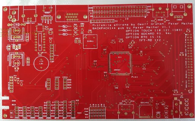 Underside shows the 40-way GPIO pinout to the MMX (and the solitary 22uF capacitor!!) 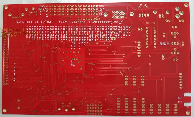 A couple of silkscreen teething errors have already been fixed by Peter (Thanks Peter  ) )More photos top follow shortly . . . . WW |
||||
| WhiteWizzard Guru Joined: 05/04/2013 Location: United KingdomPosts: 2991 |
The first one has just been assembled this morning . . . (still need to tidy some SMD joints on all the decoupling caps) I ordered the incorrect onboard piezo so it is unpopulated in the photo  Notice the 'HeartBeat' LED on the lower edge (honestly - it is flashing which means the module is 'alive') 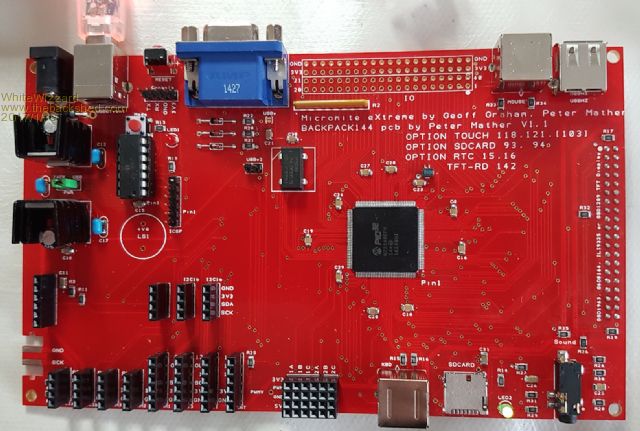 Now to connect a console/PC . . . |
||||
| WhiteWizzard Guru Joined: 05/04/2013 Location: United KingdomPosts: 2991 |
As with all Geoff's 'inventions' (and Peter's code), it just works first time . . . . .... running at 252MHz 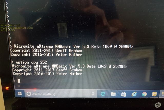 |
||||
| WhiteWizzard Guru Joined: 05/04/2013 Location: United KingdomPosts: 2991 |
Now where do I begin   The assembled green PCB in the picture is the original prototype (no mouse connector, no Nunchuck connector, no buzzer) I still have to test the completed PCB (VGA, SSD, SD, I/Os, RTC . . . ).This will take some time so I will not ship any pre-orders just yet. I will keep you all updated on this thread with progress . . . . WW |
||||
| isochronic Guru Joined: 21/01/2012 Location: AustraliaPosts: 689 |
A feast !  Any schematic ? I guess the size is about 100x150mm ? |
||||
| WhiteWizzard Guru Joined: 05/04/2013 Location: United KingdomPosts: 2991 |
Hi Stu, Schematic to be posted on website when I get a moment. Size is the exact size of a SSD 7" which equates to: 181mm x 108mm (lots of gold )It could have been a bit smaller - but designed to be a perfect fit for a 7". This allows for ALL connectors to be onboard (i.e. PS2 Keyboard, PS2 Mouse, VGA, SD, 3.5mm stereo socket, Nunchuck, 40-way TFT, 40 way GPIO, all other I/Os grouped together nicely (PWM, COM, SPI, I2C), RTC, USB-to-UART . . . . . ). WW (PS: Still awaiting your delivery ) |
||||
| isochronic Guru Joined: 21/01/2012 Location: AustraliaPosts: 689 |
Looks like the post is not happening.. weird, the other two parcels that were also sent both arrived a fair time ago. I'll check address etc and try again. |
||||
palcal Guru Joined: 12/10/2011 Location: AustraliaPosts: 2039 |
For anyone in TrumpLand I found this, unfortunatel shipping to OZ is another $40.PIC32MZ Paul. Edit. OK maybe I made a mistake I thought They were about US$30 from Microchip but they are only US$13. My mistake. Paul. "It is better to be ignorant and ask a stupid question than to be plain Stupid and not ask at all" |
||||
retepsnikrep Senior Member Joined: 31/12/2007 Location: United KingdomPosts: 134 |
Oh this is exciting now.. I've got my 7" screen ready... I'll never get anything else done now.. Well done to all involved in these great projects.. Gen1 Honda Insights. |
||||
| WhiteWizzard Guru Joined: 05/04/2013 Location: United KingdomPosts: 2991 |
UPDATE: I have completed 90% of the testing I wanted to do. Working fine are: TFT VGA SD card PS2 Keyboard PS2 Mouse Nunchuck RTC PIC1454 USB-to-UART Latest Firmware from Peter is fantastic - great text orientation features now There are two issues I have uncovered - one being that a reset press is required at power-up to kick the MM into life! Am hopefully sorting this out today. The other issue is that the 5v Reg I am using runs hotter than I would expect it to when using an external PSU. I may need to change the part (currently a LM2940CT-5.0 (RS 533-8164)). This should be good for 1A, with a 6.25v-26v input.Circuit pulls approx 180mA with a VGA and approx 500mA with a TFT. The TFT makes it very hot, the VGA is surprisingly warm. This is with a 9v input and even a heatsink on the vReg. All works fine if powering from the USB input. Could be a dodgy cap somewhere - and this is currently my biggest issue. Still have a few things to test such as onboard buzzer (correct size part arriving today), WAV, and all the lower left I/O headerss (PWM, UART, SPI, I2C). Will update later today (currently Tuesday 8:15am UK time) WW |
||||
| HankR Senior Member Joined: 02/01/2015 Location: United StatesPosts: 209 |
WW, No way can this lightly sunk device handle 1 amp at 26 volts input. According to the TI datasheet an infinite heatsink will only allow 20 watts of dissipation, and that will be with the regulator running red hot! It's 1 amp and 26 volts, but not at the same time. The warm behavior you're seeing with 9 volts in and running the VGA or especially the TFT is exactly as would be expected, taking into account the need to dump the excess pass voltage-pass current product (power in watts) of the linear regulator as heat. That's roughly 2 watts of heat to get rid of in the first regulator with the TFT running and 9 volts coming in. Changing linear devices will not produce a big difference, but you may be able to shave a little on junction-to-case thermal resistance. An onboard switching regulator option is probably called for which will produce a tremendous reduction in dissipated heat. Or you just need an even bigger heatsink if you're sticking with linear regulation. Or an external switching regulator wall-wart input for people running the TFT screens. (Everyone knows what a wall-wart is.) Hank |
||||
| WhiteWizzard Guru Joined: 05/04/2013 Location: United KingdomPosts: 2991 |
Hank, Thanks for your comments - and they pretty much repeat what Peter Mather emailed me at the time I posted the above comments. Peter uses a 7.5V PSU which is more suitable from a 'heat perspective'. My preference is to use a 5v PSU into the USB socket and with a PS2 keyboard and either a TFT, or VGA output. This way there is near zero heat from the 3v3 vReg. Am busy testing still . . . . |
||||
| WhiteWizzard Guru Joined: 05/04/2013 Location: United KingdomPosts: 2991 |
A big acknowledgement needs to go to Peter who is frantically busy squashing a few final 'issues' that I uncovered in testing. Sorry Peter for finding these - but best squashed now I guess. Guys - you are going to love the next release of MMBASIC This is yet more great work by Geoff and Peter  |
||||
kiiid Guru Joined: 11/05/2013 Location: United KingdomPosts: 671 |
Looks like someone is getting paid for advertisement... or maybe overly too excited. http://rittle.org -------------- |
||||
| WhiteWizzard Guru Joined: 05/04/2013 Location: United KingdomPosts: 2991 |
That would be nice !! No, I am simply spending many man-hours testing each release that comes out - and therefore am fortunate enough to spend time seeing and playing with the new features. Many of the things mentioned a few weeks/months back on TBS as features 'that would be nice to have' are included thanks to Geoff's attention to detail; and Peter's desire to drive graphics forward. I will stand corrected if you guys don't enjoy the new MMBASIC v5.3  |
||||
| WhiteWizzard Guru Joined: 05/04/2013 Location: United KingdomPosts: 2991 |
UPDATE: The mystery I had with the MMX requiring a reset prior to waking up has been solved by BIGMICK (annoyingly for me while he was sitting on the sofa watching TV on the other side of the planet!!!) A big thanks to BigMick  And the graphical software issues I had have been solved by Peter. So testing can continue (still awaiting delivery of the buzzers). One slight component sourcing issue is being worked on. Need to find a 24MHz DIL Oscillator in stock that runs at 3v3. We have work-arounds - but aiming for 'perfection'! Time to play some tunes with the MMX . . . WW |
||||
| matherp Guru Joined: 11/12/2012 Location: United KingdomPosts: 11513 |
For the avoidance of any doubt I don't make any money from any aspect of the Micromite. I don't get any sort of royalty on software, PCBs or anything else. I don't sell anything myself and the "financials" of any boards I have designed that are sold by anyone else are entirely their responsibility - I provide the designs free and completely open source. I will release the gerbers and DesignSpark design files for the Backpack144 as soon as I am completely happy they need no further modification. The Micromite eXtreme firmware source, which of course is still largely Geoff's code, will be freely available exactly the same as Geoff's MM+ and uM2 code and under the same licence conditions. |
||||
| Cremo Newbie Joined: 21/07/2015 Location: ItalyPosts: 36 |
Talking of 5v regulator when I have problem of dissipation I use a switching device with TO220 pinout ( larger than TO220) that works well with a 7" display. It is the ROHM BP5275-50 The problem is cost: �8.63 at Digikey. A cheaper device is RECOM R-78E5.0-0.5, cost �2.73 each. Best regard. Pietro |
||||
| panky Guru Joined: 02/10/2012 Location: AustraliaPosts: 1127 |
Peter, Please don't be put off by the unfortunate remarks of kiid - I believe everyone on TBS is in awe at the speed with which you develop enhancements and solutions and very appreciative of your generosity in providing them to everyone free. From me personally, a very greatfull thank you for your contributions - I have 4 of your 470 designed boards and they work a treat - waiting with great anticipation for the MZ board to arrive Thanks also to Phil for making the ideas into end products.Regards, Doug. ... almost all of the Maximites, the MicromMites, the MM Extremes, the ArmMites, the PicoMite and loving it! |
||||
| WhiteWizzard Guru Joined: 05/04/2013 Location: United KingdomPosts: 2991 |
The MMX144 PCB is very much Peter's design. My involvement has mainly the many man-hours of stress testing of the firmware, and also of the PCB design - with just a few suggestions; some of which Peter has kindly implemented Have been busy testing WAV and Sound stuff tonight - it is sounding great! |
||||
| The Back Shed's forum code is written, and hosted, in Australia. | © JAQ Software 2026 |
