Notice. New forum software under development. It's going to miss a few functions and look a bit ugly for a while, but I'm working on it full time now as the old forum was too unstable. Couple days, all good. If you notice any issues, please contact me.
WhiteWizzard Guru Joined: 05/04/2013 Location: United KingdomPosts: 2962
Posted: 10:36pm 19 Jan 2017
Copy link to clipboard
Print this post
MicroMite eXtreme 144 Module: UPDATE
Thanks to everyone who has been in touch and who have shown their support.
GREAT NEWS: The PCB was ordered Wednesday evening and is currently in fabrication as I type this message. The fabrication process status is showing as 60% complete; and is due to be finished in the next 3 hours. I have spoken with the factory this morning and they have ensured me that the PCBs will be despatched prior to them going on the Chinese New Year Holiday.
The 250MHz PICs are on schedule to arrive today via UPS in the next 4 hours; and most of the other components arrived yesterday (UK Thursday). Any outstanding bits will be ordered next week on a 24hr delivery basis.
So with a bit of luck, the PCBs should arrive here in the UK sometime mid-late next week.
Will update you again with anything significant as and when appropriate . . .
WW
WhiteWizzard Guru Joined: 05/04/2013 Location: United KingdomPosts: 2962
Posted: 11:45pm 19 Jan 2017
Copy link to clipboard
Print this post
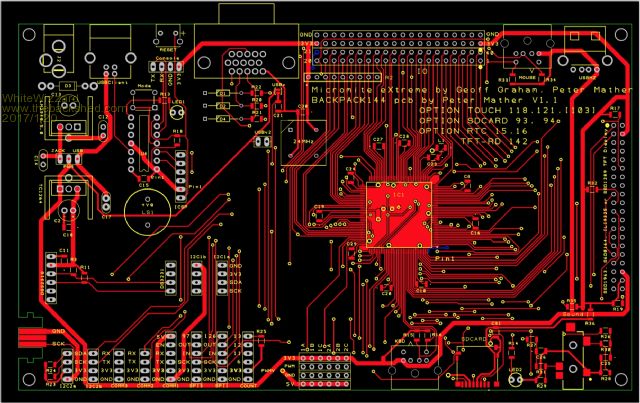
Here is a graphic for the Top layer & Silkscreen,
Working clockwise around the edge of the PCB (from Top Left corner): - Power input socket - USB Client (Type B) communication socket (and Power option) - Reset switch - VGA output socket - I/O Connector (Digital/Analogue) + Power connector for external 'stuff' - PS2 Mouse socket - USB Host socket (for future use!)
- 3.5mm Stereo jack socket (WAV & tone output - line level) - HeartBeat LED (think of this as a flashing Power LED - It can be disabled (turned off)) - uSD Card socket - PS2 Keyboard socket - PWM connection headers - COUNT connection headers - SPI1 - SPI3 - COM 1 - COM 2 - COM 3 - I2C2 (x2 headers)
- Nunchuck edge-connector - DS3231 Socket - Power selector jumper (between the two heatsinks/vRegs) to select Power source (Power Jack, or, USB)
Other points to note: - Towards the upper left corner is the PIC1454/5 USB-to-UART circuit complete with 'Mode' button, and 'Mode LED' - I2C1 (x2 headers) are to the right of the RTC (and above the two SPI headers) - On board buzzer (above RTC) - Heavy duty vRegs complete with mechanical heatsinks - Console connection (should you need it!) to the left of the VGA socket - ICSP header to the right of the buzzer / PIC1454/5
Mounting holes are located for direct mounting onto a 7" TFT (tested with SSD)
One last thing for those who have pre-ordered: The 250MHz PICs have just arrived
WW
cdeagle Senior Member Joined: 22/06/2014 Location: United StatesPosts: 268
Posted: 12:00am 20 Jan 2017
Copy link to clipboard
Print this post
Excellant work Geoff, Peter and Phil.
Looking forward to using this system.
Zonker Guru Joined: 18/08/2012 Location: United StatesPosts: 772
Posted: 01:08am 20 Jan 2017
Copy link to clipboard
Print this post
Wow.. Nice layout...
So, the RTC uses the same module as the E-100 board.. I did order 2 of them... I think I see some tracks going to the other side.. Are you using the memory IC part of the RTC module..?
Thanks Gent's..! This is ant awesome design project
MMX..! Sweet..!!
WhiteWizzard Guru Joined: 05/04/2013 Location: United KingdomPosts: 2962
Posted: 01:21am 20 Jan 2017
Copy link to clipboard
Print this post
Hi Zonker;
A word of warning regarding the use of E100 'configured' RTCs on the MMX.
On an E100, the RTC 'pins' are effectively facing downwards so that the RTC battery ends up 'sandwiched' between the E100 PCB and the RTC PCB.
On the MMX, the RTC pins are reversed meaning the battery needs to be facing 'upwards' (i.e. not sandwiched between the PCBs).
So both the E100 and MMX 144 can use the same RTC module - but the pins need to be installed either upwards, or downwards, to match the MM PCB accordingly. If not, the RTC memory gets very hot, very quickly!!
Alternatively, leave the pins at right angles (as normally supplied from the Chinese suppliers), then you can plug the RTC into either PCB, however, the RTC will be at right-angles to the MM PCB and hence not very 'low profile'
Hope this all made sense . . . .
WW
Zonker Guru Joined: 18/08/2012 Location: United StatesPosts: 772
Posted: 01:05pm 20 Jan 2017
Copy link to clipboard
Print this post
Thank you fine Sir..!
I would have not noticed it, and cooked it..
I took the RA pins out of the E-100 RTD module and fitted up the straight ones...
I will be doing the same for the new MMX PCBA... (did we name this one?)
Is the I2C memory IC wired in..? Code to use it..?
Thanks again WW for your feedback on this..!
WhiteWizzard Guru Joined: 05/04/2013 Location: United KingdomPosts: 2962
Posted: 01:49am 21 Jan 2017
Copy link to clipboard
Print this post
UPDATE regarding MicroMite eXtreme 144 Modules:
- The PCB factory has finished the fabrication of the MMX144 PCBs
- DHL have picked up the consignment from the factory (1hour before factory shut down for New Year!)
- Estimated delivery date to me in UK is Thursday 26th Jan
I will let you know the minute they arrive . . . .
Zonker: The memory chip on the RTC is addressed/accessed via the same pins as the RTC. I remember there being some code somewhere on TBS to access this memory - but it is something I have not 'played' with personally.
There is an OPTION RTC 15,16 setup command to automatically let MMBASIC talk to the RTC. With this set, I do not know if the memory can then be accessed.
I will communicate with Peter Mather regarding this to clarify . . . . .
WW
WhiteWizzard Guru Joined: 05/04/2013 Location: United KingdomPosts: 2962
Posted: 03:35am 21 Jan 2017
Copy link to clipboard
Print this post
@Zonker
Good news about accessing the Memory chip. Here is Peter's response:
Zonker Guru Joined: 18/08/2012 Location: United StatesPosts: 772
Posted: 08:51pm 21 Jan 2017
Copy link to clipboard
Print this post
Ok.. Thanks Gent's.. Will look into in...
On the E-100 I dint think it was wired in... I didn't see any tracks going to the smaller connector..
Grogster Admin Group Joined: 31/12/2012 Location: New ZealandPosts: 9932
Posted: 09:01pm 21 Jan 2017
Copy link to clipboard
Print this post
The smaller connector on the RTC module, is just a repeat of some of the connections on the other side of the module, so they are only there for mechanical support of the module, and nothing else. You can use either side, in other words.Smoke makes things work. When the smoke gets out, it stops!
WhiteWizzard Guru Joined: 05/04/2013 Location: United KingdomPosts: 2962
Posted: 03:14am 22 Jan 2017
Copy link to clipboard
Print this post
MMX144 PCBs have cleared Customs in Hong Kong
ETA is still quoted as 'By End of Day, Thursday 26th January'
I know it is 1 year after... but ... Is there still a chance for getting 1 or 2 MMX144 PCBs? I guess there is always a person like me on every forum... ;/
edit: Now I'm in contact with WhiteWizzard and it looks I'm on the way to get my own MMX...Edited by mallorn 2018-01-15