Notice. New forum software under development. It's going to miss a few functions and look a bit ugly for a while, but I'm working on it full time now as the old forum was too unstable. Couple days, all good. If you notice any issues, please contact me.
Phil23 Guru Joined: 27/03/2016 Location: AustraliaPosts: 1667
Posted: 11:46am 02 Jun 2017
Copy link to clipboard
Print this post
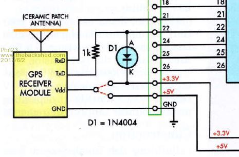
So what's the disadvantage of doing the hardware solution like Geoff uses in most of his GPS projects? It was what I had in mind for all my HC-12's, which I'd rather run on 5V, so there's less load on the 3.3V supply.
Phil.
JohnS Guru Joined: 18/11/2011 Location: United KingdomPosts: 4335
Posted: 12:10pm 02 Jun 2017
Copy link to clipboard
Print this post
Do you mean to have GPS Vdd at 5V?
What is the max voltage drop A-K when TxD is high i.e. what is the max volts on pin 22?
(And is it within PIC32 spec?)
I take it that the 1k is intended to provide a current limit? But as there are apparently no clamping diodes in the PIC32 is the 1k guaranteed to work?
JohnEdited by JohnS 2017-06-03
WhiteWizzard Guru Joined: 05/04/2013 Location: United KingdomPosts: 2991
Posted: 02:45am 03 Jun 2017
Copy link to clipboard
Print this post
Perhaps I've missed something - but why not remove this pull-up on the Dout, and then simply add your own to 3v3. Then can feed into MM input.
piclover Senior Member Joined: 14/06/2015 Location: FrancePosts: 134
Posted: 12:46pm 03 Jun 2017
Copy link to clipboard
Print this post
@Phil23
In your schematic, the 1N4004 diode (200V/1A rectifier diode) is an overkill, and being a Silicium diode, it will only clamp at 0.7V or so above Vdd, which is beyond specifications for a PIC 3.3V inputs.
I use small BAT85 Schottky diodes for such a clamping (will clamp at around 0.3V above Vdd, i.e. within specs).