Notice. New forum software under development. It's going to miss a few functions and look a bit ugly for a while, but I'm working on it full time now as the old forum was too unstable. Couple days, all good. If you notice any issues, please contact me.
Andrew_G Guru Joined: 18/10/2016 Location: AustraliaPosts: 883
Posted: 11:50am 20 Aug 2017
Copy link to clipboard
Print this post
Hi Hank, any chance of an image with it in FU2 mode. And that is definitely spelt "two" and not "too".
(I recall Robert Rozee's notes saying that once you put them into FU2 mode the speed cannot be changed from 4800. That is NOT my experience - does anyone have a comment on this?)
Andrew
HankR Senior Member Joined: 02/01/2015 Location: United StatesPosts: 209
Posted: 02:27pm 20 Aug 2017
Copy link to clipboard
Print this post
I don't think it would be worth trying to photograph because the triggering wasn't as stable as for FU1 and some other technical factors.
The pulse rate in FU2 is so slow I counted it by eye and timed a bunch of pulses and got the frequency that way! Three of my counters were struck by some kind of plague and are out of service so no help from them.
All you have to do is take the maybe 2.5 msec wide pulses you see here and space them out to .5 second and that's it for FU2 idle mode. With sleep mode on it looked about the same and I definitely have a hard time believing it dropped to anything like 22 from 80. It's possible I wasn't getting it into sleep mode by I did do some verification that showed it was.
Well, we're dealing with attaining fairly large differences in average current when doing energy minimization so the exact numbers aren't so very important in this context. The HC-12 average FU2 idle current estimated by the scope trace is something like 60 uA and that is good enough to be getting up into years of life with your circuit as it is without taking any further measures like reducing measurement frequency or using the day/night sensor.
Last but not least the reason for going to the scope was that the DMM was going wild with readings jumping up and down. I knew that this was the reason why before hooking up the scope setup, but it was a complete surprise that the pulses go right up to the normal idle 16 mA even in the feeble microamp sleep mode.
The DMM reading of the FU1 idle was rock solid even though that one has hefty pulses. I wonder if the DMM reading is as accurate as we would normally expect of a normal DC reading, given that spikey waveform. We're not looking for an RMS but an average value. I think I'll avoid using a good old fashioned moving coil meter on these spikey waveforms in case it could even remotely cause some damage. From a few dozen microamps to a dozen or so milliamps is quite a factor of overload.Edited by HankR 2017-08-22
Grogster Admin Group Joined: 31/12/2012 Location: New ZealandPosts: 9975
Posted: 02:32pm 20 Aug 2017
Copy link to clipboard
Print this post
I guess this is becasue the HC-12 is waking up periodically to see if there is any data to process.
"No? OK, I'll go back to sleep." kind of idea, so the 20mA pulses represent the waking state when it is looking for data in the buffer perhaps?Smoke makes things work. When the smoke gets out, it stops!
Andrew_G Guru Joined: 18/10/2016 Location: AustraliaPosts: 883
Posted: 03:40pm 20 Aug 2017
Copy link to clipboard
Print this post
Hank and Grogs, thanks. Yes my DMM was being "erratic" but I was seeing lower readings each time I tried something new. I'll keep trying. Cheers, Andrew
HankR Senior Member Joined: 02/01/2015 Location: United StatesPosts: 209
Posted: 04:08pm 23 Aug 2017
Copy link to clipboard
Print this post
G,
I'm thinking about an answer to what you're calling the waking state, but for the moment I'd like to point out a small misimpression that you (and others) possibly have with the scope display image.
The 20 mA and 20mS labels show what 2 major vertical and horizontal divisions represent, respectively, not the amplitude of the pulse nor the time between pulses.
So the pulses are 16mA high, just as the spec sheet tells.
The very short answer to what the 16mA does is to look for the presence of an RF signal. It's before there's even any decoded data to buffer.
I'm pretty sure this is why there's vague language in the translated spec sheet about needing longer data packets with the power saving modes because the HC-12 is off and doesn't just wake up if there is a valid RF signal any old time. It has to be in that brief pulse interval, and at the lowest current mode that only happens TWICE a second -- super slow even by my standards. The receiver of the RF IC alone needs 13 mA.
I would conjecture that no one here has ever used an HC-12 in any power saving mode. Very easy to lose data that way for sure.
For transmitting only, as for Andrew's app, there is no need to ever turn the receiver on at all using up that 16 mA. That kind of real deep sleep would be a good addition to the selectable modes of the HC-12.
Hank
Andrew_G Guru Joined: 18/10/2016 Location: AustraliaPosts: 883
Posted: 01:36pm 24 Aug 2017
Copy link to clipboard
Print this post
Hmmm, interesting point Hank. Is it possible to disable the receive circuit to save power? Eg desolder something or cut a track? But I bet there is no circuit diagram available.
I would suspect that many/most applications would have a battery powered remote and powered base station?? (I'm still trying to get around to measuring sleep currents (my leg is healing well but I had a fall yesterday with a dog doing a U-turn under my crutches) no harm done.)
I'm thinking that a rechargeable AA sized LiFePO battery (600mAh 3.2V) might be an idea? Cheers, Andrew
Grogster Admin Group Joined: 31/12/2012 Location: New ZealandPosts: 9975
Posted: 02:33pm 24 Aug 2017
Copy link to clipboard
Print this post
I have not been able to find a schematic of the HC-12, and I have looked. If anyone DOES have one, or knows where to find one, I would also be very interested to see it.
The HC-12 uses a transceiver IC(the little square chip), and the receive/transmit mode is fully controlled by the MCU on the HC-12(the SSOP chip). It HAS to be when you think about it, so I don't like your chances of disabling just the receiver.
It is most likely done with one single pin. Pull high for transmit, pull low for receive kind of concept. You could download and study the datasheet for the transceiver chip.Smoke makes things work. When the smoke gets out, it stops!
HankR Senior Member Joined: 02/01/2015 Location: United StatesPosts: 209
Posted: 04:16pm 24 Aug 2017
Copy link to clipboard
Print this post
All commands to the RFIC, including switching from R to T, are done through its SPI port which is why it's so nice to have a little host uC to take care of all that.
Andrew, to summarize your present situation now that I've measured the low power mode drain of the HC-12 (~60 uA), that puts your total drain of the circuit at ~100 ua given a typical sleep current for the Micromite of 40 uA. The pulsed transmit contribution to average current depends on the HC-12 transmit current (programmable) and duration. If that's held to 30 mA for 1/10 second every 10 minutes it will be negligible compared to the steady 100uA.
For a 2500 mAh AA, you're already at 2.8 years, so I think you've already arrived without any further changes. I think your inflated current drain was caused by faulty DVM response to the pulsing nature of the HC-12 drain.
An actual running time test using AA cells will not show any discernible change for many, many weeks. It will of course show a vast improvement in just a week or two over what you started with.
Using AAA zinc carbon cells (~500 mAh by WIKI) will speed the test up and require about 1/5 the time to see a discernible change in voltage. The trouble with going even lower by using a small button cell is that those are not really designed for 16 mA loads and thus the test results might be inaccurate, although it would quickly establish a worst case lifetime.
The zinc carbon AAA test should show some significant voltage droop in a month or so which makes it quite practical for getting some results.
Andrew_G Guru Joined: 18/10/2016 Location: AustraliaPosts: 883
Posted: 05:53pm 20 Sep 2017
Copy link to clipboard
Print this post
Hi again. An update: My 2x AA-powered remote (an MM170, a DS18B20 and an HC-12) is still working after 4 weeks but the battery voltage has dropped from 3.2V to 2.93V. It can't keep going much longer!
I've included the code for the remote below and the circuit is as per the first post except that the DS18B20 is now powered "Direct" rather than "Parasitic". I've set the HC-12 to FU-2 mode at 2400 baud and have included all the above power saving suggestions (except a 3rd AA battery which I can't fit in this jiffy box).
A month's life is OK but are there any more suggestions?
Cheers,
Andrew
HC-12 Remote code:
'HC-12 Remote ID4 x 2400 at 10min.bas ' Uses a 28 pin MM170 to take temperature readings via a DS18B20. ' An HC-12 is used to transmit the readings to a base station which displays the readings from several remote stations. ' Each remote station is identified by an ID - this code is for station No. 4. ' 'Notes to self: 'Don't forget the <CR><LF> at the end of NMEA sentences 'I use zzz to flag code I need to check 'Steps to reduce power consumption: ' - set all unused pins to DOUT - done ' - only send a temperature every 10 minutes and then put the MM and HC-12 to sleep in between - done ' - only send a temperature if it differs from the previous reading - done (code commented out below) ' - HC-12s to power mode FU2 (necessitates 4,800 or 2,400 baud) - done using Rob Rozee's HC-12 Configuration program ' - Set baud rate to 2400 to increase range - done ' - Set the MM to a slow speed - reduced MM to 20 (any slower & TEMPR returns "1000" = error) ' - Don't need to ground unused pins - not grounded
Dim Integer Chksum Dim Float Temp, TempOld Dim String StationID = "4" 'Apply a unique No to each remote station (ID 1 = Base Station) CPU 20 'Set the CPU's speed to the slowest that still enables a TEMPR reading
'Set all unused pins as DOUT 'Leave pins 1, 8, 11, 12, 13, 18, 21, 27 and 28 alone for now SETPIN 2, DOUT SETPIN 3, DOUT SETPIN 4, DOUT SETPIN 5, DOUT SETPIN 6, DOUT SETPIN 7, DOUT
SETPIN 9, DOUT SETPIN 10, DOUT
'SETPIN 14, DOUT 'Pin 14 used as the HTC-12 SET signal so is to be set as DOUT anyway SETPIN 15, DOUT
'Pin 16 is used by the TempR command so leave for now SETPIN 17, DOUT SETPIN 18, DOUT
'Pins 21 & 22 are set by the Com#1 Open and Close commands so leave for now SETPIN 23, DOUT SETPIN 24, DOUT SETPIN 25, DOUT SETPIN 26, DOUT
Open "COM1:2400" As #1 'Com1 uses pins 21 and 22 for Tx and Rx respectively. 4,800 required for mode FU2. TempOld = 0 'Gets checked each reading. Only sends a value if it differs. PIN(14) = 1 'zzzProbably unnecessary??
Do 'The main loop - it never ends SendTemp 'Read and send the temperature via the HC-12 to the base station
' put the HC-12 to sleep PIN(14) = 0 'Set pin low to enter SETUP mode Pause 50 'Wait at least 40m seconds Print #1, "AT+SLEEP"
'GetResponse 'Check that it responds "OK+SLEEP" - used in debugging PIN(14) = 1 'Return the 'SET' line high again to exit SETUP mode
' put the MM to sleep Close #1 CPU SLEEP 599 'Here to set the CPU sleep time in seconds (600 = 10 minutes)
'After a sleep - the MM wakes up. Then wakeup Comms and HC-12 Open "COM1:2400" As #1
'To wake up a sleeping HC-12, you have to pulse the 'SET' line low again(50mS should do it), 'then return the line high again and WAIT 200mS for the module to reset itself. PIN(14) = 0 ' pin is set low - this enters Command mode Pause 50
'then return the line high again and WAIT 200mS for the module to reset itself PIN(14) = 1 ' pin is high Pause 200 ' HC-12 should now be OK to receive/send data Loop End
Sub SendTemp Local String Out$ Local Integer Z Temp = TEMPR(16) ' If Temp = TempOld then 'zzz Omitted whilst testing battery usage ' Exit Sub ' Else ' TempOld = Temp ' EndIf
Out$ = CRC$("$,"+Str$(Temp)+"," + StationID) 'This is close to an NMEA 0183 "water temperture" sentence $??MTW... with the StationID exchanged for "C" (Celsius) Print Out$ Print #1,Out$ ' pause 250 'Print #1,Out$ 'zzz Appears to be not needed 'Send it a second time 'Pause 250 End Sub 'SendTemp
FUNCTION CRC$(Txt$) 'AS String 'Returns the Txt$ passed to it with "*hh" added, where hh is the NMEA Hex checksum Chksum = 0 FOR n = 2 TO LEN(Txt$) 'n=2 makes it skip the leading $ Chksum=Chksum XOR ASC(MID$(Txt$,n,1)) NEXT n CRC$=Txt$+"*"+HEX$(Chksum,2) END FUNCTION
'Sub GetResponse 'Only used when debugging to check response to "AT+SLEEP" = "OK+SLEEP" ' Local integer i ' Local string x$ ' Tmp$ = "" ' Do ' X$ = Input$(1,#1) ' If X$ = Chr$(13) then ' Exit Sub ' End If ' Tmp$ = Tmp$ + X$ ' Loop 'End Sub
Grogster Admin Group Joined: 31/12/2012 Location: New ZealandPosts: 9975
Posted: 06:10pm 20 Sep 2017
Copy link to clipboard
Print this post
I never got around to sleeping the HC12 via the AT+SLEEP command and playing with the SET line, but can I assume that you got it working fine?
I assume you have - at some point - checked that the current consumption drops off to a very small figure once you issue that command, yes?
I plan to use this very same "Software-sleep" method on a project using an HC12 very soon, so it would be nice to know if the theory about sleeping the module actually works. Smoke makes things work. When the smoke gets out, it stops!
Andrew_G Guru Joined: 18/10/2016 Location: AustraliaPosts: 883
Posted: 08:03pm 20 Sep 2017
Copy link to clipboard
Print this post
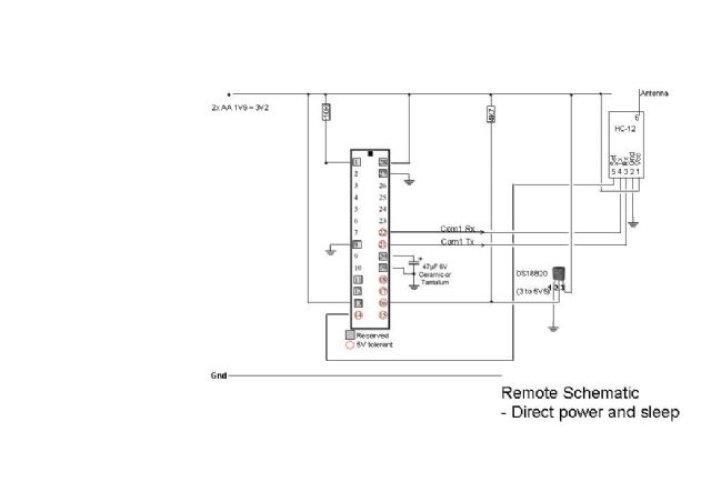
Hi Grogs, I believe that the above code puts it to sleep - in the end it wasn't too hard, even for me (my code above seems to work). If you use the last dozen lines of code, commented out above, it certainly reports "OK+Sleep". I have achieved twice the battery life (and still going). But, using my historic DMM I could only detect that the sleep current was less; but could not get a repeatable reading - if you look a few posts above HankR reports that the sleep current is not steady but is actually a series of pulses which average to the values given in the specs (hence my confused DMM). My remote schematic is:
Cheers, Andrew
HankR Senior Member Joined: 02/01/2015 Location: United StatesPosts: 209
Posted: 11:17pm 20 Sep 2017
Copy link to clipboard
Print this post
Andrew,
I have one basic recommendation and a comment or two. It's going to be about circuit considerations rather than software from now on.
You're using too high an endpoint voltage for the life of the device and its battery. When I provided a battery life estimate it was based on a much lower endpoint voltage. I thought you'd be implementing the third AA cell as suggested before.
I think you really have to not let the present box size dictate an unrealistic and ineffective design as you now have. You pretty much have to increase the voltage of the battery to something like a minimum of 4.5 volts. Adding the popular MC1703 regulator will use an insignificant (compared to the high Micromite sleep current) quiescent drain of around 1 uA.
Now you can tolerate some realistic droop of the battery and still have the device running okay, both the uC and the transmitter components. The uC can go way under 3 volts, but the HC-12 can't, therefore the 3 volt supply has to go. Out!
The droop of the two AA cells still seems too high, although much better from where you started a while back with a 2 day total life!
As I've asked you to do before, it's really necessary for you now to get some steady current readings and these you can do with your DMM. I would like you to measure the sleep current of the MMite and the running current of the MMite. The sleep current is the more important reading, but you might as well do both while you're at it.
This is not as critical but if you added just a little test code, you could have the circuit report to you over the serial port the time the whole awake cycle takes in milliseconds. Same for the HC-12 activation and sleep subcycle. Again, these are second order importance measurements, but nice to have at this point in the development cycle.
I might have to finally get a MMite so I could do some of these measurements, because there is still something not right going on.
It's good, but it should be a few more months I believe for that kind of voltage droop to manifest.
Oh, one question. Were those fresh AA name brand cells? I would guess they were based on the 3.2 start voltage.
Hank
CaptainBoing Guru Joined: 07/09/2016 Location: United KingdomPosts: 2171
Posted: 11:18pm 20 Sep 2017
Copy link to clipboard
Print this post
Well done Andrew
one thing to try is dynamically altering the CPU speed.
see your SendTemp Sub,
play around with something like this:
CPU 20 pause 100 Temp = TEMPR(16) CPU 5
so you only run the cpu fst when you need to. The little delay lets everything settle but then it all goes back to a miserly 5MHz when you are doing mundane/non-time-critical stuff. The serial is only jogging along at 2400 so you shouldn't have any problems
Just an idea to try and eke out a few more mA. Another trick I have used in the past was to actually power-down extraneous devices with a 2N7000 on their power rail so they are really "off". if you have a spare output you could try this really easily
HankR Senior Member Joined: 02/01/2015 Location: United StatesPosts: 209
Posted: 11:57pm 20 Sep 2017
Copy link to clipboard
Print this post
It's quite counterintuitive, but slowing the CPU speed when sleep is involved can actually increase total energy consumed per unit time rather than decrease it.
When a large sleep to wake cycle ratio is employed, as is here, the extra time while awake caused by a slower uC clock is guaranteed to increase the energy use. It won't be a big difference with this application, but the main point is there is no gain to be had.
The gist of the explanation is this: Slowing the clock by a factor of four does not decrease the current by as much as a factor of four. Because the uC now takes 4 times the awake time as before, but uses more than one-fourth of the current as before, the total energy used in the wake cycle is increased.
Even if the wake current with a slowed clock was directly proportional to the clock speed, there would be no decrease in energy consumed. It would be exactly the same.
Slowing the clock only helps (a lot) with consumed energy if there is continuous awake operation of the uC.
Hank
HankR Senior Member Joined: 02/01/2015 Location: United StatesPosts: 209
Posted: 12:38am 21 Sep 2017
Copy link to clipboard
Print this post
I have to take the above back because I see there are many pauses of hundreds of milliseconds built in the software that consume wake time independent of clock speed. Even without them the fixed time the HC-12 needs to transmit is a contributor to wake time independent of clock speed, so there is some gain to be had in slowing the 20 MHz clock after taking the one wire temperature measurement as Captain has suggested.
It's going to be diluted by the fact that over the period of the 10 minute measurement cycle, the total sleep current of the MMite and the HC-12 is a large contributor to total energy consumed in that 10 minute span, and thus the average power consumed by the device.
So a halving of wake cycle energy will not halve the overall average energy consumed per unit time; there will be some lesser reduction. That's what I mean by dilution.
I won't do that arithmetic before knowing the interval times I asked Andrew to measure using software. I will say that I used 1/10 second before as the wake time of the whole system, just as an arbitrary guess value without looking at the code, for estimating the AA battery life (in a prior post). So that means I was too low entirely with that number since there are 200 and 250 millisecond pauses in the code. So all the pauses alone take up more than half a second.
That wake time really needs to be measured for a decent detailed energy calculation.
Hank
CaptainBoing Guru Joined: 07/09/2016 Location: United KingdomPosts: 2171
Posted: 12:39am 21 Sep 2017
Copy link to clipboard
Print this post
agreed and your points are valid - it is all about "sweet-spots" and they are non-linear - work/time is not a 1:1 function of energy
this is all about experimentation... I would still try everything to get a reduction
Edited by CaptainBoing 2017-09-22
crez Senior Member Joined: 24/10/2012 Location: AustraliaPosts: 153
Posted: 04:45am 21 Sep 2017
Copy link to clipboard
Print this post
When testing very low current drain circuits with pulsing current levels, it is sometimes useful to run them from a supercap and watch the voltage drop over time. Using the relationship current x time = capacitance x voltage change
rearrange to I=cv/t where v is the change in capacitor voltage. I=amps, c=farads, t=seconds
Using a 1 Farad cap, a 1mA current drain will result in a drop in the voltage of 1mV per second, or 60mV per minute. For example, if the circuit supplied from the 1F cap dropped the voltage from 3.5v to 3.2v in 5 minutes, the current drain must be (3.5-3.2)/(5*60)=0.001 ie 1mA.
Having such a large cap on the supply is likely to cause problems with booting the micromite due to a slow rise of the supply voltage, so charge the supercap before connecting it to the circuit.
At really low current levels, you can't keep a multimeter on the capacitor voltage continuously without affecting the results.
HankR Senior Member Joined: 02/01/2015 Location: United StatesPosts: 209
Posted: 08:18am 21 Sep 2017
Copy link to clipboard
Print this post
Andrew's design is really very good. The only area left to be refined is the average current is higher than he'd like and higher than I think can be attained with his basic present circuit allowing for perhaps a tweak or two.
My intent always is to use the numbers, along with the basic principles, to illuminate the mechanisms at play whatever aspect of a circuit is being explored.
The very practical value of knowing the principles is to be able to most effectively put one's time and effort into only those methods that will gain worthwhile circuit improvement. And to do the best methods first, and then the lesser methods later until one is satisfied with the circuit's performance.
Another great value is knowing when, practically speaking, the law of diminishing returns is kicking in and all the reasonably worthwhile improvements have been made and the designer has reached the limits essentially of what can be accomplished with the constraints imposed. There are always some constraints, even in the hobbyist domain: cost, weight, size, cost, input power, etc.
So it's basically informed experimentation and is applicable to the hobbyist.
Hank
kg4pid Regular Member Joined: 08/03/2015 Location: United StatesPosts: 50
Posted: 08:58am 21 Sep 2017
Copy link to clipboard
Print this post
To the orginal poster, the weather station I am wanting to build looks just like your design with the addition of a few more sensors. I have been reading the post here with interest since I have been trying to figure out the best way to power everything.
My dying Davis Vantage Pro II used a couple of super caps charged by a solar panel along with a CR2 or CR123 (can't remember) for extended periods of no sun. I will be watching your progress.
Max
Andrew_G Guru Joined: 18/10/2016 Location: AustraliaPosts: 883
Posted: 12:22pm 21 Sep 2017
Copy link to clipboard
Print this post
Hi all, Thanks for your interest and help. I'll take the measurements that Hank suggests (it will take a few days) and I’ll use a breadboard to build another circuit with: - easy access to measure currents - 3x AA batteries (with voltage regulator to 3.3V) - a transistor to sever the power to the rest of the circuit during sleep (I’ll be interested if the start-up current balances out the savings? - any comments anyone?) - I can easily reduce the CPU speed to 5 whilst the MM is asleep - I can change the reporting frequency from once every 10 minutes to say 15, 20 or 30
(I take Hank's comment about the point of diminishing returns but these seem easy and viable)
I'll shortly start a thread to illustrate what I do with the data.
Cheers,
Andrew
Page 2 of 3
Print this page
The Back Shed's forum code is written, and hosted, in Australia.