
|
|
Forum Index : Microcontroller and PC projects : Help with LORA modules
| Author | Message | ||||
| CaptainBoing Guru Joined: 07/09/2016 Location: United KingdomPosts: 2171 |
interesting link in my news feed this morning: https://www.thethingsnetwork.org/article/ground-breaking-world-record-lorawan-packet-received-at-702-km-436-miles-distan ce?source=techstories.org |
||||
| srnet Senior Member Joined: 08/08/2014 Location: United KingdomPosts: 164 |
Indeed and the trackers are very simmple too. The TTN and GPS code will run on a Arduino PRo Mini (�1.50). That report was for 868Mhz too so although they were using 4dB more power than permitted at 434Mhz, the path loss at 434Mhz is 6dB less, implying that the equivalent range on 434Mhz @ 10mW would be 880kM or so. I once thought of doing a Micromite LoRa tracker. $50SAT is Silent but probably still working. For information on LoRa visit http://www.loratracker.uk/ |
||||
OA47 Guru Joined: 11/04/2012 Location: AustraliaPosts: 1044 |
I received the LoRa modules yesterday and have come to a brick wall in trying to establish a link between the modules. I believe that they are transmitting as I can see a substantial increase in current draw when I apply data but I don't see any reception either way. The documentation is in Chinglish and shows easily established communications using the supplied configuration and testing apps. I have read through the manual many times but I am still missing a setting somewhere albeit the documentation suggests that they should link up with the default configuration. Any guidance or suggestions from shedders very welcome. Graeme |
||||
Grogster Admin Group Joined: 31/12/2012 Location: New ZealandPosts: 9931 |
Check your local regulations. I guess this works OK in Australia, but any New Zealand members reading this - according to the data, 915MHz STL's are no longer licensed in NZ, so you CAN use 915-928MHz for LoRA, but stay well clear of the 890-915MHz cellphone band, or RSM and the affected telco will come down on you like a ton of bricks if you mess with their commercial cellphone services.  I'm actually gonna get a couple of the 915MHz version of that module to test on the spectrum analyser to see how they go and to see what their output is like. I was suitably surprised by how clean the HC12's were, so I am hopeful for these ones next. I will post photos when I do this. The 915-928MHz band in NZ is allowed a reasonably powerful 0 dBW(1W, 1000mW, 30dBm) - starting to be an attractive band for this stuff if you are allowed that kind of power!  EDIT: @ Graeme - Can you post the manual(s) here, or a link to them, and I(and probably others) will take a look and see if we can decipher them. I'm gonna need them anyway for my modules. Smoke makes things work. When the smoke gets out, it stops! |
||||
| srnet Senior Member Joined: 08/08/2014 Location: United KingdomPosts: 164 |
I have not used those UART front ended modules. I do know a fair bit of detail on how to drive the LoRa device itself (which is SPI based) and for packet based stuff they are easy enough. One thing to watch, if your using the SPI device you dont have to worry about corrupt data as the packets can be CRC enabled, not sure about the UART front end modules its possible they dont use CRC checking. $50SAT is Silent but probably still working. For information on LoRa visit http://www.loratracker.uk/ |
||||
| OA47 Guru Joined: 11/04/2012 Location: AustraliaPosts: 1044 |
E32-TTL-100 The configuration and testing apps are under DOWNLOADS-TOOLS |
||||
| KeepIS Guru Joined: 13/10/2014 Location: AustraliaPosts: 2091 |
Basic CRC error checking is a function of the user packet data and independent of hardware, inbuilt error correction is obviously a function of the device firmware and hardware and should be independent of the device interface. NANO:Inverter V 8.2ks - Linux AvrDude GUI script V4.1 |
||||
| davematt Regular Member Joined: 27/09/2011 Location: AustraliaPosts: 55 |
@Graeme I too was hoping the modules would work with the default settings, but no luck. I'm sending 2400 baud, and can see something received, but it's not recognisable. Assume you have M0 and M1 grounded? Trying the config software today, will let you know... Dave |
||||
| OA47 Guru Joined: 11/04/2012 Location: AustraliaPosts: 1044 |
Here is a snap of the hardware test set up I have. There may be something extremely obvious that I have missed.  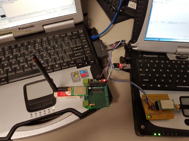 |
||||
| KeepIS Guru Joined: 13/10/2014 Location: AustraliaPosts: 2091 |
Just out of interest, what do you have the PC interface serial Baud rate set at? NANO:Inverter V 8.2ks - Linux AvrDude GUI script V4.1 |
||||
| OA47 Guru Joined: 11/04/2012 Location: AustraliaPosts: 1044 |
Last I checked it was 9600,n,8,1 for the PC serial port. |
||||
| KeepIS Guru Joined: 13/10/2014 Location: AustraliaPosts: 2091 |
Then looking at the data sheet and the steps you have posted, the dam things should be communicating, I've had problems before with some RF devices with respect to packet size and RX/TX stalling, I guess you have tried sending one byte (character) at a time instead of a packet, I always go back to square 1 with these things and try to establish the simplest connection if things are acting up. Wish I could be of more help. Mike. NANO:Inverter V 8.2ks - Linux AvrDude GUI script V4.1 |
||||
| OA47 Guru Joined: 11/04/2012 Location: AustraliaPosts: 1044 |
Yes Dave I have links to ground on the left unit and DIP Switches on the right unit as belts and braces I have included 10k pullups. I have a LED on the AUX pins and this does indicate when data is transmitted from either unit but I do not get a response when receiving. Here is the config screen. The only change I have made is the output power which was set at 20dbm out of the packet. 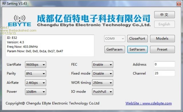 |
||||
| OA47 Guru Joined: 11/04/2012 Location: AustraliaPosts: 1044 |
I have made a breakthrough......... I do have a link  Now to see if the Micromite can join in. |
||||
| Grogster Admin Group Joined: 31/12/2012 Location: New ZealandPosts: 9931 |
C'mon, Graeme, you code-tease - tell us what you did to make the link work and what you were doing wrong!  Smoke makes things work. When the smoke gets out, it stops! |
||||
| srnet Senior Member Joined: 08/08/2014 Location: United KingdomPosts: 164 |
Yes, I realise that. I have come across UART front ended modules that turn off the RF devices own error checking, so you need to implement your own based on the UART\Serial data stream. $50SAT is Silent but probably still working. For information on LoRa visit http://www.loratracker.uk/ |
||||
| OA47 Guru Joined: 11/04/2012 Location: AustraliaPosts: 1044 |
I will fess up. I had confused one of the bus tracks on the arduino prototype board and the LoRa module would not be able to stay in mode 0. I should have twigged earlier as the unit on the Freetronics prototype board would sometimes go into config mode without switching the M0 & M1 leads. Any way this is a start: 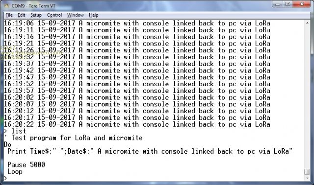 I am not sure that editing a program at this data rate will be successful but I will have a play with different settings to see if I can get a more usable system. |
||||
| Grogster Admin Group Joined: 31/12/2012 Location: New ZealandPosts: 9931 |
Ahhhh. Nice one.  I'll be interested to hear back from you as to what range you actually get from them while I wait for my ones to arrive. I'll be interested to hear back from you as to what range you actually get from them while I wait for my ones to arrive.Smoke makes things work. When the smoke gets out, it stops! |
||||
| CaptainBoing Guru Joined: 07/09/2016 Location: United KingdomPosts: 2171 |
related/intersting http://www.theregister.co.uk/2017/09/14/printable_iot_radios_for_10_cents_each/ |
||||
| OA47 Guru Joined: 11/04/2012 Location: AustraliaPosts: 1044 |
Grogs, I did a very scientific range test. With the units set at 10dB power and the transmitting unit on a test bench in the steel clad back shed, I went for a walk to the back gate which is over a hill and about 150 meters from the shed. As the photo shows there were some dropouts but software could distinguish them. 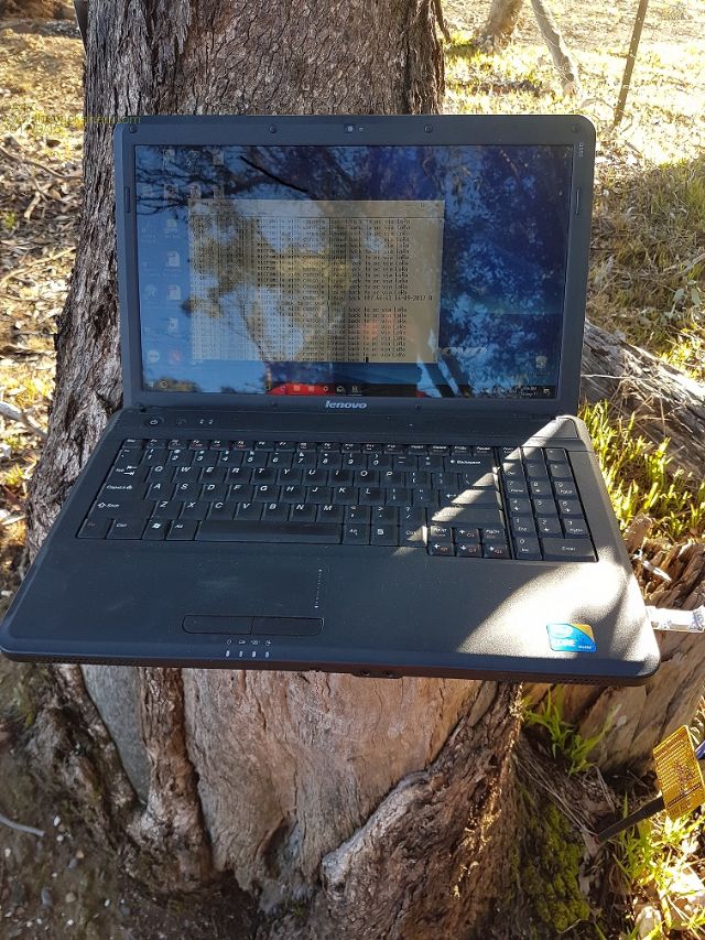 |
||||
| The Back Shed's forum code is written, and hosted, in Australia. | © JAQ Software 2026 |
