
|
|
Forum Index : Microcontroller and PC projects : Why doesn’t this work?
| Author | Message | ||||
| Warpspeed Guru Joined: 09/08/2007 Location: AustraliaPosts: 4406 |
Yup, exactly right. There are a few different solutions. Often rotary switches use a wiping type of contact which works fine for low power signal switching. Contacts that do not have a wiping action can use gold plated contacts. Gold being very soft and not forming a natural oxide layer can work reasonably well. The very best signal switching relays, used for example in high end data loggers, are always reed contacts, and sometimes mercury can also be used in fully sealed mercury relays to help the contacts to bridge very reliably with very low closed resistance. Completely electronic switching is always preferred these days, especially using mosfets. I thought I could get away with using relays with gold plated contacts, but it did not work. Switching significant power burns off the gold plating very quickly, then the relay contacts are only good for switching power and useless for high impedance signal switching for ever after. I sort of knew all this, but decided to try it anyway, but without success. Cheers, ĀTony. |
||||
redrok Senior Member Joined: 15/09/2014 Location: United StatesPosts: 209 |
Hi Alastair;On Topic: That is why I had suggested the use of a small capacitors across the contacts to cause the tiny "Cleaning" spark. The wiki article also mentions the use of these capacitors. I understand this didn't work though. There must be something else that is wrong. Maybe the oxide or oil film is to strong to be broken down. Off Topic: Hi Warpspeed;I have done this also: However I needed to use relays because the battery string was over 120VDC. Clearly, I couldn't use analog switches because of the high voltage. The DPDT dual coil latching relays I used had gold contacts, (I got 500 for aout $100us). I was measuring individual cell voltage with the "Flying Capacitor" technique. The gold contacts don't have an oxide so work even at very low voltages. Whetting problems just don't exist. However, the contact resistance does vary a bit. For an even better relay ones with sealed "Mercury Wetted" contacts are superior. 1. There can be no oxide layer in the liquid mercury. 2. The contact resistance is both lower and consistently un-changing than even the gold types. Back on topic: I've been trying to figure out why the circuit works WITHOUT a pullup but NOT with a pullup. This just makes no sense. OK, this is a wild concept with several odd circumstances: 1. The is a bit of "Leakage Current" on the board. There has to be something to cause the pin to see a high when the switch is off. This leakage current has the equivalent resistance, possibly, many megOhms but enough to cause a HIGH on the pin. 2. (The weird part) The switch has capacitance between the terminals. This capacitance varies depending on the position of the ball. In fact the capacitance can have quite a few pF when the ball is supposed to close. (It doesn't actually make contact because of the tiny insulating layer.) This increase in capacitance in series with the small pin capacitance forms a voltage divider and causes the voltage on the pin to get low enough to look like a LOW on the pin. This scenario actually fits the facts. 1. 100K PU isn't able to break down the oxide. 2. Yet it works with an even higher PU resistance, the leakage current. It turns out the 100K PU is actually the lower valued resistance compared to the many megOhm leakage resistance. redrok |
||||
| Warpspeed Guru Joined: 09/08/2007 Location: AustraliaPosts: 4406 |
[quote]Clearly, I couldn't use analog switches because of the high voltage. [/quote] My battery is 100v (x30 3.3v lithium cells) Analog switches work fine, mine are rated for 350v blocking voltage. They can also be fully protected with a 100mA fast blow fuse if two try to connect simultaneously to different cells along the battery cell chain. I also use a flying capacitor isolator, with excellent results. Cheers, ĀTony. |
||||
Grogster Admin Group Joined: 31/12/2012 Location: New ZealandPosts: 9975 |
I do have one unit(out of ten) that with the pullup option off, trips as soon as you put the battery on. This is with the ball-switch in the neutral position, and so the pin is NOT pulled to ground, but the unit just trips over and over and over - exactly what it is supposed to do, when the ball-switch is active. I fixed THAT one, by putting back the pullup option. That done, THIS one then works as it should. I think redrok might be onto something with the 'Ball-switch is actually a capacitor' idea....... Smoke makes things work. When the smoke gets out, it stops! |
||||
Quazee137 Guru Joined: 07/08/2016 Location: United StatesPosts: 603 |
Just a thought can you go the other way do PULLDOWN and have the switch goto 3.3v and look for a high or Interrupt on low input to high. |
||||
| redrok Senior Member Joined: 15/09/2014 Location: United StatesPosts: 209 |
Hi Quazee;Sure, that would work, sort of. But, in the big picture, none of these "Fixes" to a flawed circuit will cut it in the long run. Teaching Moment: The processor is basically a CMOS chip with very high input resistance. There are several general rules to follow: 1. No pins should be left "Floating". The voltage on the pin is in-determinant. The value is dependent on factors such as: A. Minute "Leakage Currents" will be flowing over the board. Even very clean boards will have some leakage current flowing from the supplies lines or neighboring pins. This is pretty much unavoidable. It can be controlled with guard traces to specific voltages but even then the leakage is still present. B. There is capacitance between all pins. This capacitance may be small but is never zero. CMOS pins switch relatively fast. This couples small current pulses between pins. These pulses can be rectified by the pin protection diodes causing unexpected results on the pin. 2. Pins should always be connected to other low impedance circuit elements or have pullups, whether internal or external. A. For active pins internal 100K pullups are generally sufficient but sometimes lower value external pullups may be required. B. All unused pins MUST have a determinate state. Internal pullups, direct connection to ground/Vdd, or setting the pins as outputs are required. Yes it's a pain and you can probably get away not doing it but you run the risk of funny things happening, especially if you give this to someone else. If your going to sell it good engineering practices are MANDATORY. 3. Sensors should be fully understood so they have a chance to do what they are designed to do. A. Not all specs fully explain their parts limitations. The tilt switch we have been discussing probably needs to have relatively high current flows to reliably make contact. We often see switches fail if the currents are to low. But, there are are switches designed to switch these low current signals. redrok |
||||
| Quazee137 Guru Joined: 07/08/2016 Location: United StatesPosts: 603 |
Sometimes you need to look for a high as in this rallyman's problem they talked about using the pulldown of the pin and look for a low to high. and one more dipswitch |
||||
| Warpspeed Guru Joined: 09/08/2007 Location: AustraliaPosts: 4406 |
Redroc is quite right. Mickey Mouse solutions are not going to make the fundamental problems go away. Cheers, ĀTony. |
||||
| Quazee137 Guru Joined: 07/08/2016 Location: United StatesPosts: 603 |
Not sure how this falls under 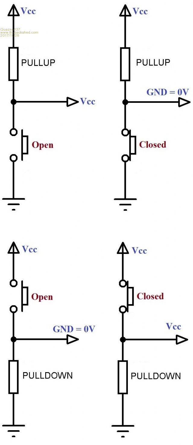 They work as needed. and sometimes you want to ensure the state of an output before the the pins are setup. 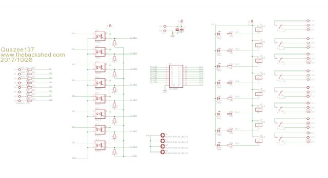 you want the relays to be off on power up. |
||||
| Grogster Admin Group Joined: 31/12/2012 Location: New ZealandPosts: 9975 |
I used to use pulldown resistors, and have the switch(sensor or otherwise) pull the input high to trip it, but I swapped and went the other way a few years ago because of a PICAXE project that would false-trip with that arrangement, as that was a system that used 4-core security wire as a 12v bus and a trip line, and it was discoivered that inductive coupling from neaby mains cables under load in the roofspace, coupled into the cable and was causing the input to see that induced voltage as a high, and would respond in kind.  ...so I changed to grounding the input pins, as induced voltage is not a problem in that arrangement(generally). Here we go again...... I like the reed-relay and swinging magnet idea and I am playing with that, but I MUCH prefer an all-in-one solution without having to build up a bits-a arrangement like that. Hense why I was drawn to the ball-switch which is an all-in-one solution.  I am now thinking that what I might do for an experiment, is take a suitibly low value resistor, and use that as an external pullup(disable the internal one) such that when the ball-switch is active, it WILL be sucking at least a few mA from the supply, which should solve those issues and blow through any oxide layer within the switch, and at the same time, it will pull the I/O pin very firmly low with it. I will hack the prototype to see if that works, but I am reasonably confident, and it only requires adding one single resistor. The problem with the INTERNAL pullup option is it's relatively high resistance prevents any kind of current flow to break through any oxide issues with the ball-switch, or so it would seem. The units are working fine with NO pullup at the moment, but as redrok mentioned(and I also mentioned earlier), that leaving inputs floating makes me nervous and I would rather not do that in the interests of good design practise. I will keep the thread updated.  Smoke makes things work. When the smoke gets out, it stops! |
||||
| Quazee137 Guru Joined: 07/08/2016 Location: United StatesPosts: 603 |
May be trying a sealed version will work keeping all else the same. tilt sw or tilt sw 2 the problem may be only in the switch being unsealed. was adding parts and saw the opto library and got an idea.  |
||||
| JohnS Guru Joined: 18/11/2011 Location: United KingdomPosts: 4335 |
Those are great and should work but the problem looks to be that they're not an accurate or appropriate representation of the ball switch. (If only!) John |
||||
| Warpspeed Guru Joined: 09/08/2007 Location: AustraliaPosts: 4406 |
The "Mickey Mouse" part has nothing to do with the pull up or pull down resistors. But with what is supposed to make a good RELIABLE electrical contact. A mercury tilt switch might be the easiest solution. https://www.ebay.com/sch/items/?_nkw=Mercury+Tilt+Switch&_sacat=&_ex_kw=&_mPrRngCbx=1&_udlo=&_udhi=&_sop=12&_fpos=&_fspt =1&_sadis=&LH_CAds=&rmvSB=true Cheers, ĀTony. |
||||
| Grogster Admin Group Joined: 31/12/2012 Location: New ZealandPosts: 9975 |
Hi chums. I also have some of those green axial switches, but they only close a circuit in one direction, not both as the ones I am using do. That is easy to fix by using two of those axial switches though. I would expect that they probably have the same oxide-layer problem as the ones I am using at the moment do. Liquid mercury switches are not something I would want to use, as if they break, you have liquid mercury contamination which is not a good thing. The previous design of this thing did used those exact same mercury switches in glass, but they got broken and you would collect them for service, open them up and find liquid mercury running around inside the unit. I wanted to avoid that, so mercury switches are out, sorry. Perhaps if I could find suitably encapsulated ones so the mercury can't get out like they can if you break the glass ones.... I will have a hunt on the web. Smoke makes things work. When the smoke gets out, it stops! |
||||
| Warpspeed Guru Joined: 09/08/2007 Location: AustraliaPosts: 4406 |
I have never seen potted mercury switches, but it would not be a difficult thing to do yourself. Otherwise it has all the virtues. Cheers, ĀTony. |
||||
| Grogster Admin Group Joined: 31/12/2012 Location: New ZealandPosts: 9975 |
That's a thought! I could pot some! Nice one. Might look at that idea.  Smoke makes things work. When the smoke gets out, it stops! |
||||
TassyJim Guru Joined: 07/08/2011 Location: AustraliaPosts: 6538 |
40+ years ago we used mercury tilt switches to make grazing recorders for cattle. To make them survive life in the paddock, we potted them in perspex. Drill a hole, insert the mercury switch and fill with "Acrifix" Acrifix is a great product to use when playing with perspex and it is still available 40 years on... You end up with the switch inside a clear perspex block. The Acrifix removes all the drill marks giving a very professional result. The cattle were very happy with them. Jim VK7JH MMedit |
||||
| Warpspeed Guru Joined: 09/08/2007 Location: AustraliaPosts: 4406 |
I often wondered how the transparent perspex block trick was done. Very helpful, thank you. It would not take much, a piece of suitable perspex tube cut to length, and one end blocked. Insert the mercury thingy, and fill with Jim's magic goo. Cheers, ĀTony. |
||||
| redrok Senior Member Joined: 15/09/2014 Location: United StatesPosts: 209 |
Hi Warpspeed;Or another you could use a different Non-Acrylic plastic: I've used a short piece "Clear Vinyl Tubing" to encase things like sensors to make them water tight. 1. Using a heat gun melt one end and squeeze it with a pliers. 2. Insert the sensor with bare wires coming out. 3. Melt and squeeze the other end. Wallah, water tight, and presumably leak proof. This works very well and isn't as brittle as the hard plastics. And you don't need the special plastic welding glue. Note: 1. Both vinyl and the acrylics are fairly good in sunlight but should be protected from direct sunlight. 2. Polystyrene plastic is hopeless in sunlight and should never be used. redrok |
||||
| Warpspeed Guru Joined: 09/08/2007 Location: AustraliaPosts: 4406 |
Funny you should mention welding clear vinyl tubing around wires. I recently had trouble with the automatic defrost system in my refrigerator. There is a thermal fuse wired in series with the defrost heating element, so that if the evaporator gets too hot during defrost, it open circuits and shuts off the heater. The interesting thing is that that thermal fuse was encased in clear vinyl tube, and the ends appeared to have been heated (welded) and clamped closed around the wires. I was wondering how they did that without triggering the 75C thermal fuse. But it certainly made a very tight impressive looking waterproof seal around the wire. Important because the thermal fuse runs at 240v and may become embedded in solid ice. Cheers, ĀTony. |
||||
| The Back Shed's forum code is written, and hosted, in Australia. | © JAQ Software 2026 |
