
|
|
Forum Index : Microcontroller and PC projects : simplest 32MX150 ICSP
| Author | Message | ||||
| JohnS Guru Joined: 18/11/2011 Location: United KingdomPosts: 4335 |
Ooh, which board has the 170F? Is flashing a umite taking around 20 mins? Not too awful, if so. John |
||||
| robert.rozee Guru Joined: 31/12/2012 Location: New ZealandPosts: 2528 |
my feeling is that the most important 47pF capacitor is the one on PGC, which can be placed pretty much anywhere, at either end. it serves to help prevent any false clock pulses being induced from elsewhere (crosstalk). peter: you may be able to squeeze a little more out of your code by sticking to short variable names and avoiding constants of the form &h0, &h1, etc. just use 0, 1, etc. remember, the interpreter needs to interpret every character in variable names and constants. you could also try the following code from Keith.W and see if it is any quicker: Pin(clk)=1 'first clock SetPin pgd,dout 'Programmer PGED output on Pin(pgd) = tdi Pin(clk)=0 'latch tdi into chip Pin(clk)=1 'second clock Pin(pgd) = tms Pin(clk)=0 'latch tms into chip SetPin pgd,din 'as chip tdo active soon Pin(clk)=1 'third clock Pin(clk)=0 'enable chips TDO tdo=Pin(pgd) 'as data was ready after fall of clock 3 Pin(clk)=1 'fourth clock Pin(clk)=0 repeat for each transaction. this code will work ok on the micromite without any delays because of the speed limitations of interpreting each line - the interpreter runs at about 23,000 lines per second, or 43uS per line. unless you have a suitable resistor in series with PGD, you always need to configure pin(PGD) as an input before the rising edge of the 3rd clock pulse. and under all circumstances you should always retrieve the value of PGD before the rising edge of the 4th clock pulse. those who say otherwise are just wrong, wrong, wrong... rob :-) |
||||
| robert.rozee Guru Joined: 31/12/2012 Location: New ZealandPosts: 2528 |
peter: you may also be able to improve speed by hard-coding the pin numbers. ie, if you are using pin 4 as PGD and pin 5 as PGC, then use the following code: SETPIN 4,DOUT PIN(4)=0:PULSE 5,.01 'TDI=0 PIN(4)=0:PULSE 5,.01 'TMS=0 SETPIN 4,DIN PULSE 5,.01 TDO=PIN(4) PULSE 5,.01 going to sleep now... rob :-) |
||||
| G8JCF Guru Joined: 15/05/2014 Location: United KingdomPosts: 676 |
John It's incidental that I'm using a 170F, it could just as well be a 150F. The brains behind it all is a Windows program. All that's in the uMite are the low level operations and the pseudo instructions. My last burn time was well over 1 hr ! hence my questions above. I'm making changes to both the uMite prog and the Windows prog in an attempt to reduce the time. @RR I really don't want to have to squeeze the uMite code so that it becomes an unmaintainable bowl of spaghetti ! I will now have to roll out my pre-processor so that I can keep long variable names in the source, constants etc, but in the run-time code downloaded to the uMite, the preprocessor will replace all that long stuff with short forms, and the constants with numeric values. In developing my BCD libraries I spent weeks trying the different ways of optimising code, and I found for example that &H constants were always faster than decimal constants amongst other things, accessing a value in a numeric variable was always slower than accessing an &H constant - I was surprised by that since I had assumed that once the numeric variable had been loaded with a value, the interpreter would not have to do the ascii to bin conversion every time it needed the value, so C=10:A=2*C should have been faster, but in fact A=&H2*HA was faster. 73 Peter The only Konstant is Change |
||||
| JohnS Guru Joined: 18/11/2011 Location: United KingdomPosts: 4335 |
I know it's incidental but which board? I don't own a 170 and would like one! (Preferably cheaply and fairly soon.) John |
||||
| G8JCF Guru Joined: 15/05/2014 Location: United KingdomPosts: 676 |
Oh, Jim sent me an actual PIC32MX170F256B chip to thank me for developing the ByPIC Plugin Maker software. I don't actually know if Jim is selling them yet, but I think he's going to replace the 150F in his BV500 product (just a chip) with 170F. The 170F ByPIC has additional features including � You can now pass arrays into functions � Global variables share program space � All devices are boot loadable � Floating point (single) The free flash is huge !! I guess if you contact Jim, you can arrange something with him. 73 Peter The only Konstant is Change |
||||
| JohnS Guru Joined: 18/11/2011 Location: United KingdomPosts: 4335 |
That explains why when I hunted all round their site & shop I couldn't find it! John |
||||
| G8JCF Guru Joined: 15/05/2014 Location: United KingdomPosts: 676 |
Sorry, I should have said. Apologies Peter The only Konstant is Change |
||||
| JohnS Guru Joined: 18/11/2011 Location: United KingdomPosts: 4335 |
Peter - No worries! rob - I stuck a 1K across the 3K3, giving about 767 ohms and cut delays (then stuck a tiny one back in to make it work). Time to flash a umite dropped from 69 secs to 40. (Confirms the resistor inserts a delay as it was said to.) No apparent nastiness and I'm still with the original mare's nest of wires. May not need the 100R and cap after all. Thanks for the help, everyone. Looking OK. Next to make it work with 4 wires (no 1K/3K3) and/or a Windows host... John |
||||
| Keith W. Senior Member Joined: 09/10/2011 Location: AustraliaPosts: 118 |
About Pulses. Peter, 32 bit integer c/w 32 bit shift built into MMBasic would be beneficial again in your program here as found when controlling DDS, and the ability to call code subroutines. Noting that you used the PULSE command within your program caused me to wonder about any overhead in using Pulse instead of driving the output pin on and off directly. Could we save a little time? When using a Micromite at 40 MHZ and Version 4.5 MMBasic. Executing : - Ploop: Pin(clk) = 1 Pin(clk) = 0 Goto Ploop The resulting waveform was high for 70 microsecond and low for 100 microseconds. I surmised that the Goto was adding the extra 30 microseconds. Placing five positive and negative transitions in the program before the Goto confirmed this. Altering the commands to Pin(15) , instead of Pin(clk), sped the rate by about 1% to my frequency meter, noticeable but not critical. With the code: - Ploop: Pulse(15), .01 Goto Ploop I observed correct 10 microsecond pulses but at a rate of 150 microseconds spacing. Subtracting 30 microseconds for the Goto and the 10 microsecond pulse width gives 110 microseconds overhead for setting the pulse command. This confirmed by placing more pulse commands before the Goto. Therefore the PULSE method just wins for short pulses, for a 10 microsecond pulse the total program delay is 120 microseconds against 140 microseconds for quickest direct pin twiddling. With a pulse width of more than 30 microsecond direct drive has less overhead. Of course with direct drive the minimum width is 70 microseconds. Increasing the PULSE width slowed the repetition rate while retaining the 110 microsecond setup time between pulses. With one million pulses to program the chip, at least 4 per bit without verifying, there goes 120 seconds in just pulsing alone. Well it was a thought, and interesting findings. Keith. |
||||
| JohnS Guru Joined: 18/11/2011 Location: United KingdomPosts: 4335 |
Another small step: moved to 4-wire (ditched the resistor and use bidi PGD), again an 80MHz PIC32 which is programming a umite. Need the same delay and overall again 40 secs. I think I could move to a smaller delay (min. is now 1us) and might test that. The delay is where I set PGC low. I think otherwise I have a pulse on PGC which is too short (and won't meet the min spec in the datasheet). So all is good. John |
||||
| WhiteWizzard Guru Joined: 05/04/2013 Location: United KingdomPosts: 2991 |
So John, you can load MMBasic 4.5D into a blank PIC32 in 40seconds. Is that correct? What is your exact target PIC currently based on this timescale of 40s? (28/44pin MX150/170?) I love keeping an eye on this thread . . . . So much for those people that said it can't be done! 
Excellent progress - keep it up 
|
||||
| JohnS Guru Joined: 18/11/2011 Location: United KingdomPosts: 4335 |
Currently MX150 (44-pin) as I haven't got a 170! The software is now in 2 main variants: 1. slow via USB serial (FT232RL) 2. fast via a PIC32 #2 is a Pinguino32 OTG (it's what I had lying around) - it basically is told what to do by the host PC (it could be standalone but then where does the hex come from?) In both cases I'm programming a umite that has a MX150. I've also tested programming a MX220 but it's only 32K flash so pretty quick, not much of a test. Now it works I'll tweak the Pinguino version to run on a umite and then a umite can program another umite. (It's only a few port I/Os to change.) Variant 2 can use 5-wire (with a resistor on outgoing PGD) or 4-wire ICSP. (Well, the USB one also can do 4-wire but it's horribly slow.) The variants share a lot of code, thankfully. Oh - strictly it's not a umite as it's another board but it does have a 44-pin MX150. Both variants can program any PIC32MX. I don't have a 32MZ to try. John |
||||
| WhiteWizzard Guru Joined: 05/04/2013 Location: United KingdomPosts: 2991 |
If you would like a MX170 to try them PM me your shipping address and I will gladly send you one to play with. Simply let me know your preference - 28-pin or 44-pin. WW |
||||
| ajkw Senior Member Joined: 29/06/2011 Location: AustraliaPosts: 290 |
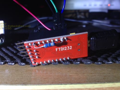
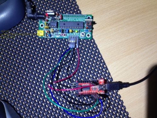
RE: the USB to FT232L method Could someone please check my set up. Programming is taking some hours to do and so far I have only successfully updated 1 PIC. Other attempts have seemingly performed successfully but I am left with a unresponsive, ie MMBasic will not boot/run, chips. I have used Mick's MUP and Zonkers boards, Win 7 on a VM and Win XP on a laptop but all is equally the same slow. I know John says it is slow but others like Mick have reported programming being achieved in 10's of minutes. I don't really get why there is such a large variation in time. I believe I have set up the resistor on the FT232 board correctly. Please refer attached photo's. Even if I could get it to an hour instead of leaving it running overnight would be great. Anthony. 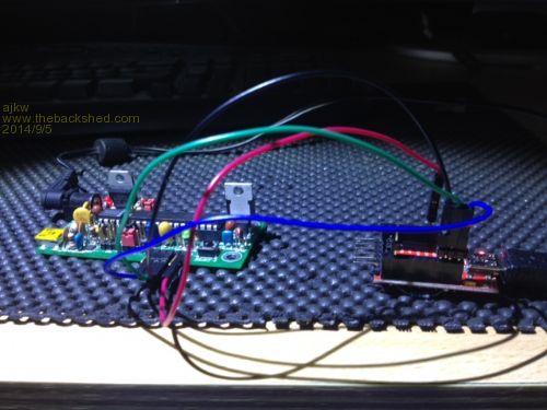
|
||||
bigmik Guru Joined: 20/06/2011 Location: AustraliaPosts: 2981 |
Hi Anthony, I have my resistor soldered like this: 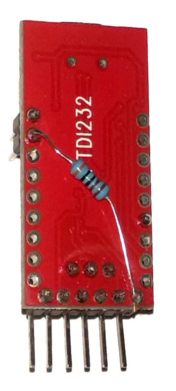
I checked with a multimeter and you have yours connected to effectively the same spot. I am using the 5V on the FTDI board to power MuP. The times I got were between 15 and 17 minutes, (I never did a `REAL' exact timing as I always missed the end) I never had a failure on my high end PC and it was consistent, I could verify it with MPLAB IPE and it worked with TeraTerm. It has been a while since I burnt one, is there a later version than the one I used (360,867 long)? I have been out of the loop for a while now. The PC I have my success with is an i7 4770 with native USB3 ports, windows 8.1 64bit and takes something less than 17 minutes to complete. (it is a DELL XPS8700). I did try an earlier version on my i7 notebook and it took over an hour and was unreliable and failed 50% of the time (sometimes at 90% mark) but that was before John added the resistor to the circuit. The problem with trying it again is it mucks up the drivers for my FT232 drivers and on win 8.1 that can be a pain to reinstate. Regards, Mick Mick's uMite Stuff can be found >>> HERE (Kindly hosted by Dontronics) <<< |
||||
| JohnS Guru Joined: 18/11/2011 Location: United KingdomPosts: 4335 |
Anthony, You asked for a Linux version so I uploaded it. Is it faster? (It is for me.) I don't have any idea why it would run so slowly for you but maybe it points to some marginal USB thing like retries. Bad cable? Try a hub? I've stayed away from powering via the FTDI board so as not to risk interfering with it. Wow, you guys do resistors neatly! Mine is shoved into one end of a (du pont) wire, then poked into the side of another. (When I went to a lower value R I poked the 2nd one into wherever it would shove.) Seems reliable :) I've not seen a (Linux) version take as much as an hour since I added the resistor and changed the software to use it. John |
||||
| ajkw Senior Member Joined: 29/06/2011 Location: AustraliaPosts: 290 |
John, I haven't yet got the Linux program to run on Ubuntu, missing some dependencies. I may try again. Which Linux are you using? I could put that on a VM. I have tried different USB cables and both direct to the back of the mainboard and via a hub. Seems to make little difference. My computer is a i7 920 cpu with USB2 only, so guess a little older than Micks i7 4770, but I can't believe the internal USB handling is that much slower. I only have a VM for Win 7 but I think my old XP drive is still in the bay so I may try plug it in and see if it still boots. I was also just thinking that I would try run the Linux version on the Pi, that lead to a thought that the Pi has GPio's... My R is now 3.3K and ftdipic32 is version "360,867" has Mick listed above, I believe the latest. I have also tried external power and power from the FTDI board. Cheers, Anthony. |
||||
| JohnS Guru Joined: 18/11/2011 Location: United KingdomPosts: 4335 |
I'd avoid VM, it's asking for delays. I don't have anything like so fast a PC. Fastest I have is core i3. I explained about Linux dependencies before. Should be trivially easy to add them. Very standard & common items. It's built for 32-bit but shouldn't be any problem at all. I've used it on different distros and once I added some common packages all was fine. (I avoid Ubuntu nowadays since they lost the plot, but should still work.) The RPi has poor USB so I'd avoid that. I may port the code there but not soon. If I get a umite (as a programmer) working at least only 1 would need the slow way as after that you could program a umite from a umite. John |
||||
| JohnS Guru Joined: 18/11/2011 Location: United KingdomPosts: 4335 |
Good offer - thanks! Will do. John |
||||
| The Back Shed's forum code is written, and hosted, in Australia. | © JAQ Software 2026 |
