
|
|
Forum Index : Microcontroller and PC projects : simplest 32MX150 ICSP
| Author | Message | ||||
| Geoffg Guru Joined: 06/06/2011 Location: AustraliaPosts: 3362 |
I was hesitant on the subject of calling machine code routines because of the difficulty of writing in assembler and then dynamically linking it into memory. But the ByPic method of using position independent C code neatly steps around that hurdle. The second issue was that people would want to have access to the internals of the interpreter (display routines, keyboard queues, etc). There are a lot of internal structures and allocating them fixed memory locations would be unsustainable. If that was specifically ruled out (as in this case) the implementation would be much easier. I am currently working on the Micromite code (for the MX170) and I will have a crack at implementing some sort of plugin architecture while I am at it. I hope that it does not turn out like PEEK/POKE which I also implemented after popular demand - then no one seems to have used it. Geoff Geoff Graham - http://geoffg.net |
||||
| WhiteWizzard Guru Joined: 05/04/2013 Location: United KingdomPosts: 2991 |
Hi Geoff, I am keeping a very close eye on this thread and IMHO I do believe this 'advanced' feature would be of immense value to those that need it. For example, personally I am currently hitting MMBasic speed limits in my RF link. I am running RF modules at just under 7kbps which is nowhere near their limit of 256kbps. From what I am reading, I would be able to get a vast improvement in speed. This has so many knock on benefits - the main one being that I could make battery powered wireless sensors as opposed to having to have mains powered sensors. Battery sensors means I can locate them anywhere; and can produce them at lower costs. The only ironic thing is I would be having to Learn C for coding in a BASIC environment  Oh well . . . . Oh well . . . .
So please if you can include this feature in your to-do list I for one would also be very grateful. 
WW |
||||
| JohnS Guru Joined: 18/11/2011 Location: United KingdomPosts: 4335 |
PEEK was quite useful in seeing how the fp math works. Not very exciting! The simpler the first kind of call-to-C the better, so people find its limitations and which ones really matter, I suspect. Not much (if any?) access to the internals, is my feeling, but it would be useful to pass simple values in and out. John. |
||||
| G8JCF Guru Joined: 15/05/2014 Location: United KingdomPosts: 676 |
Hi Geoff I think that allowing access to MMBasic internals would be a recipe for disaster. BTW, I use Peek/Poke because one can't pass arrays between functions in MMBasic. I think that this plugin capability would allow people like me to write high performance libraries which would effectively act as extensions to MMBasic. Also anyone doing realtime stuff would really appreciate the capability to execute compiled code in tight situations. Re an MMBasic plugin, being able to call the address of an INTEGER array would be the way forward IMHO. I would happily create an "MMBasic Plugin Maker" which would take the assembler/machine-code output from the .ELF file and generate the appropriate MMBasic Statements, eg Dim Add%(8) Add(0)=&H8c830004:Add(1)=&H8c820000:Add(2)=&H8c630000:Add(3) =&H8c420000 Add(4)=&H00621021:Add(5)=&H8c830008:Add(6)=&H03e00008:Add(7) =&Hac620000 Which the user would then copy/paste into their code, then using it would be something like Result=Call(Add(0), Args(0)) The implication being that MMBsic would take the "address of" Add(0) and Args(0) and call the first address, and pass the address of Args(0) as a pointer to the C function. BTW, my ByPIC Plugin Maker transparently converts MIPS JAL instructions into MIPS BAL instructions allowing user written plugin functions to call other user written functions within the plugin. Please let me know if/how I can help Thanks for considering adding this capability Peter The only Konstant is Change |
||||
| G8JCF Guru Joined: 15/05/2014 Location: United KingdomPosts: 676 |
@RR I made the change you suggested into the code and 1) It still all works ! 2) But the burn time fell by only 3 seconds unfortunately to 00:25:07 Still your suggestion results in smaller code which should execute more quickly so I'll leave your suggestion in my code and check that it works correctly in the long run. I have to admit that I really don't understand how you came to your conclusion since every timing diagram in the MCHP docs shows quite clearly that TDO becomes valid on the rising edge of the 4th clock pulse, whereas your suggestion suggests that TDO is valid AFTER the falling edge of the 3rd clock pulse and BEFORE the rising edge of the 4th clock pulse. Could it in fact be that the PIC32 clocks out TDO on the falling edge of the 3rd clock pulse, and the 4th clock pulse is required simply to synch the PIC32's internal state counters (a counter of 3 would be really awkward to implement). The existing MCHP clocking diags show that the 3rd clock pulse apparently does nothing, perhaps, the documenter/technical author got it wrong and it should have been clock pulse 4 which did nothing. Will let you know how it goes over time Thanks for the suggestion Peter The only Konstant is Change |
||||
| WhiteWizzard Guru Joined: 05/04/2013 Location: United KingdomPosts: 2991 |
I hope Geoff doesn't think us UK MicroMiters are ganging up on him!! 
I am working on a USB to PS2 keyboard adapter in which I have have had to use a PIC (16F690). The ONLY reason the PIC is required is because I can't get the required speed from the MicroMite to emulate PS2 data. HOWEVER, with the 'PlugIn' method above I would be able to use a MicroMite instead of the PIC16F690. From a programming point of view, I would prefer to use a MicroMite rather than create .asm
Two uses straight away . . . . . |
||||
| JohnS Guru Joined: 18/11/2011 Location: United KingdomPosts: 4335 |
I see rob's explanation as highly plausible. I expect the target PIC32 puts out its TDO as soon as it believes the programmer has changed its PGD to be an input. (There will inevitably be a tiny delay in putting out TDO as the PIC32 has to see an edge and the state machine has to move along to putting the TDO out, but I expect we're talking 10-30ns maybe?) hmm, can we guess what clock rate that ICSP/JTAG state machine inside the PIC32 works at? It does seem to work :) However, I think maybe IT DOES NOT if you run fast enough in C (as with 700MHz RPi). I think this is why I needed a small (maybe 40ns?) delay. Such delays don't affect an MMBasic program! John |
||||
| JohnS Guru Joined: 18/11/2011 Location: United KingdomPosts: 4335 |
If the chunk of Basic can be kept short and simple then there must be a fair chance that posting it and asking for the equivalent C has a hope of being answered :) John |
||||
| robert.rozee Guru Joined: 31/12/2012 Location: New ZealandPosts: 2528 |
peter: i reckon a 10% speed improvement isn't too shabby! i shall do my best to find a few more. i've been working off figure 5-6 on page 12 of the document "PIC32 Flash Programming Specification 60001145N.pdf" (also called the 61145N datasheet). the relevant part of the diagram is: 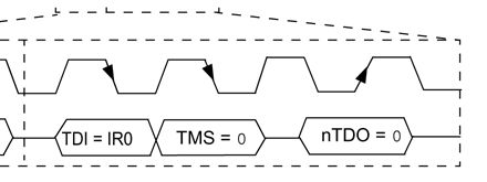
this shows TDO data becoming valid on the falling edge of the 3rd clock pulse. many people do seem to be (erroneously) assuming that TDO is 'clocked out' on the rising edge of the 4th clock pulse, without remembering that TDO is being generated by the target (the 32MX) while PGC is being generated by the host. the target needs to be told by the host to make TDO available on a clock edge, and then told that the data is no longer needed on another clock edge. it is up to the host to read the data at some time between the two edges. when the target is informed that the data is no longer needed, it needs to smartly turn PGD back into an input before the host tries forcing data onto the line. this all fits into the following 'reconstruction' that i posted a few pages back. the 8 edges of PGC can be simplified as the following list of 'instructions' to the 32MX: #1 first PGC rising edge: get ready to read TDI #2 first PGC falling edge: transfer TDI data on PGD into 32MX #3 second PGC rising edge: get ready to transfer TMS #4 second PGC falling edge: transfer TMS data on PGD into 32MX #5 third PGC rising edge: reconfigure PGD pin on 32MX as an output #6 third PGC falling edge: load TDO data onto PGD #7 fourth PGC rising edge: reconfigure PGD pin on 32MX as an input #8 fourth PGC falling edge: <end of transaction> between #4 and #5 the host needs to prepare to read TDO (configure PGD as an input at the host end). after #8 (but not before) the host is free to reconfigure PGD as an output at the host end - this needs to be done before the next #1. all as clear as mud! rob :-) |
||||
| JTR0701 Regular Member Joined: 10/07/2013 Location: AustraliaPosts: 71 |
TDO becomes valid on/after the falling edge of the phase 3 clock and remains valid up until the falling edge of the phase 4 clock. That's it really... I'm sure... This and only this explains how and why reading either before the phase 4 leading edge or after it both work. How much more evidence do we need than what has already been presented in this very thread? If it was any different how could all the code that works by testing after the phase 4 leading edge work? That includes all of microchip's programmers, my own and several of the posters here. In fact just for giggles I stuck a 30uS delay after the phase 4 leading edge before reading TDO. My programmer still worked but it was (4x slower...) Now there is still one chance at a rebuttal of this. It could be that TDO remains valid after the phase 4 leading edge simply because of stray capacitance and the high impedance state that TDO will otherwise be in. However, I tend to doubt this so much that I didn't feel the need to test out. It just seems so unlikely given all the evidence so far (like the pull-down resistors on PGC and PGD in the Pickit 2 for example...) |
||||
| JohnS Guru Joined: 18/11/2011 Location: United KingdomPosts: 4335 |
I think that diagram is - once again - slightly misleading. I think nTDO's beginning (where the level becomes a box) should be shown a little to the right to make it clear it can only start after PGC has dropped. The state machine inside the PIC32 must see that PGC drop and take a small but finite time before it manages to drive what's shown as nTDO. (With the RPi I can read TDO ever so soon after PGC drops! Doesn't work if I do.) (As before, those wretched black arrows are not helping and ought to be explained, thanks for nothing Mchp.) edit: Perhaps Mchp are trying to say that if one wanted to latch TDO (here, nTDO) then doing it on that rising edge with the black arrow would be the right time. John |
||||
| robert.rozee Guru Joined: 31/12/2012 Location: New ZealandPosts: 2528 |
alas, if you apply a vertical ruler to the timing diagram, you'll see that TDO starts to become invalid before the falling edge of the 4th clock pulse: 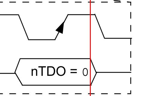
clearly the only explanation is that the 32MX looks forward in time to determine when the falling edge of the 4th clock pulse will occur, and removes the TDO drive a fraction of a second before then. them there microchip folks sure are pretty clued up on their time travel! rob ;-) |
||||
| JohnS Guru Joined: 18/11/2011 Location: United KingdomPosts: 4335 |
I think that whole box for TDO needs shifting to the right. John |
||||
| JTR0701 Regular Member Joined: 10/07/2013 Location: AustraliaPosts: 71 |
Of course if the time travel theory doesn't do it for you then there is the "sloppy work from microchip" option. Hmmm... I will have to ponder this later as right now I have to find out how the hell a police box landed on my front lawn... |
||||
| JTR0701 Regular Member Joined: 10/07/2013 Location: AustraliaPosts: 71 |
Well there has to be one in every crowd. Always someone who just has to be sensible...  |
||||
| G8JCF Guru Joined: 15/05/2014 Location: United KingdomPosts: 676 |
If one looks at the other timing diagrams, 6.6, 6.9 the falling of pulse 3 sometimes overlaps TDO and at other times misses TDO. Perhaps the MCHP technical writing team were just a wee bit slack. 5.3.1 4-PHASE ICSP In 4-phase ICSP mode, the TDI, TDO and TMS device pins are multiplexed onto PGEDx in four clocks, see Figure 5-4. The Least Significant bit (LSb) is shifted first; and TDI and TMS are sampled on the falling edge of PGECx, while TDO is driven on the falling edge of PGECx.. The 4-phase ICSP mode is used for both read and write data transfers. and yet Fig 5.4 shows the RISING edge for TDO !! Peter The only Konstant is Change |
||||
| robert.rozee Guru Joined: 31/12/2012 Location: New ZealandPosts: 2528 |
TDO is certainly driven by the target on the falling edge of the 3rd clock pulse, while to me the up arrow indicates that a relevant (to the host) state transition is triggered within the target. because the host is driving PGC, it is up to the host to read PGD during a plateau, the logical (and only completely stable) plateau being between the falling edge of the 3rd and the rising edge of the 4th clock pulses. the plateau between rising and falling edges of the 4th clock pulse covers both stable and unstable states of PGD, making this a poor time to read PGD - especially when there is (according to the datasheet) a fully stable interval in which to read. it is a bit like flying an aeroplane. you follow the instructions and instruments to the letter. you do not deviate. if you do deviate, your chances of crashing are considerably greater. rob :-) |
||||
| JohnS Guru Joined: 18/11/2011 Location: United KingdomPosts: 4335 |
Yes, but it's a bit of a guess WHY it shows it. I agree with rob & Jim that you're meant to read it such as then. Maybe a circuit which latched TDO (for software to read as and when) ought to do that on that rising edge. Some time ago it was said (and I agree) that "while TDO is driven on the falling edge of PGECx." means the falling edge of the 3rd PGECx. So what the sentence means is that the target will (start to) drive TDO out on that edge. Well, one can't read it at that instant (it will not have settled) but a little later would be OK and on the next rising edge of PGECx will be great. John |
||||
| JTR0701 Regular Member Joined: 10/07/2013 Location: AustraliaPosts: 71 |
Yes, this is exactly my position. It is IMHO common sense that just happens to be backed up by much evidence. |
||||
| G8JCF Guru Joined: 15/05/2014 Location: United KingdomPosts: 676 |
So we are settled then, TDO is stable and readable after the falling edge of the 3rd clock pulse. It's a good job we don't have edge triggered latched inputs on the PIC32 
73 Peter The only Konstant is Change |
||||
| The Back Shed's forum code is written, and hosted, in Australia. | © JAQ Software 2026 |
