
|
|
Forum Index : Electronics : Inverter building using Wiseguys Power board and the Nano drive board
| Author | Message | ||||
| mab1 Senior Member Joined: 10/02/2015 Location: United KingdomPosts: 282 |
Sorry keepis - i wasn't ignoring you - you somehow managed to sneak your reply in before mine without my seeing it when I posted.  It's 3am here now so I'm off to bed - I did try your links to programmers, but the Web browser under Ubuntu is too out of date - or the computer is too slow and times out. I'll try on the imac tomorrow and get one ordered.  hopefully I can get avrdudess to work on one computer... I'd hate to have to buy a newer one hopefully I can get avrdudess to work on one computer... I'd hate to have to buy a newer one  |
||||
| KeepIS Guru Joined: 13/10/2014 Location: AustraliaPosts: 2167 |
Absolutely no need to worry about that, never a need to acknowledge my posts, oreo posted his reply while I was still typing in any case, I really feel that it's only the driver (for the programmer) that might give you a problem in XP. Let us know as we might be able to find a workaround  NANO:Inverter V 8.2ks - Linux AvrDude GUI script V4.1 |
||||
| KeepIS Guru Joined: 13/10/2014 Location: AustraliaPosts: 2167 |
The last Solar charger arrived, now another two sets of 4 x 450W Solar panels to be Installed, one old set of panels is being replaced and this 7th charger has to be wired in with an Isolator switch and fuses, then connected to the 2nd new set of panels, along with another set of 6 gifted 300W panels for charger 6 which currently has no panels due to the rebuild of the solar controller wall and the redistribution of the existing panels. 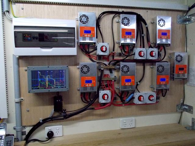 NANO:Inverter V 8.2ks - Linux AvrDude GUI script V4.1 |
||||
| oreo Senior Member Joined: 11/12/2020 Location: CanadaPosts: 133 |
My God that's a crapload of Solar Controllers! It's very neat and nicely organized too! Greg |
||||
| KeepIS Guru Joined: 13/10/2014 Location: AustraliaPosts: 2167 |
I'm a really big fan of redundancy in emergencies, and by having 4 panel per Controller they run de-rated, shading effects can be reduced as they are only 2S+2P sets of panels per controller. I bought most of these years ago when they were around $96 AU, the last one cost me $114 to my door. NANO:Inverter V 8.2ks - Linux AvrDude GUI script V4.1 |
||||
| KeepIS Guru Joined: 13/10/2014 Location: AustraliaPosts: 2167 |
@ mab1 FYI: That site oreo linked to for the other programmer board has the AVR Programming 10-pin to 6-pin cable separately for $2.25, and it fits the programmer board that I use. The programmer I used available from amazon UK with adaptor: UK Programmer with 10 to 6 pin adapter . Edited 2025-04-18 16:00 by KeepIS NANO:Inverter V 8.2ks - Linux AvrDude GUI script V4.1 |
||||
| mab1 Senior Member Joined: 10/02/2015 Location: United KingdomPosts: 282 |
cor! I wake up and find you've done the work for me!Think I'd used up my last brain cells last night: couldn't work out what to search for for the programmer, and forgot that the (relatively modern) smartphone would be the device to search for it. |
||||
| KeepIS Guru Joined: 13/10/2014 Location: AustraliaPosts: 2167 |
On thing I wanted to mention about test mode since a few of us are using this for initial testing, never forget to turn the Power supply down every time to a very low voltage or zero "before" removing the DC leads to the Inverter. Some times we forget and just unplug the DC power leads, there is no protection for large caps that you may have on the Power board when suddenly connecting the Inverter back up to high DC voltages. If you have a current limited supply set below a few amperes or say a 40 ohm 5w resistor in series with the DC input in test mode, you might get away with it, but it's still best to always lower the test power supply voltage. This is especially important if a Contactor is wired in and you put the Controller in test mode, ideally the Contactor should be disconnected in test mode, it will suddenly engage as soon as enough pull-in voltage for the Contactor is reached, with a current limited supply, this causes the supply to rise and then limit as the Contactor energizes, the Contactor drops out and then the cycle repeats. I've put some limiting and forced reset conditions in test mode but you really should not be using it unless connected to a limited low current adjustable supply or series resistor. Another gotcha is testing the complete Inverter (with big caps) and a Contactor in Test mode with an adjustable supply, then forgetting the controller is in test mode when you hook the Inverter back to the batteries and throw the big ON switch, the Contactor can still pull in at a low voltage (seems almost instant) with a huge current surge (depending on cap size). Even though I have protection for that in the Code - With Murphy at play he just might void your Warranty. . Edited 2025-04-20 10:49 by KeepIS NANO:Inverter V 8.2ks - Linux AvrDude GUI script V4.1 |
||||
| KeepIS Guru Joined: 13/10/2014 Location: AustraliaPosts: 2167 |
This may or may not be of interest: I was recently testing what effect High Inverter current with associated voltage fluctuations have on my LiFePO4 Battery bank. DSO and differential probe connected across the main DC bus between the Battery and Inverter at various locations. I'm looking at 100Hz ripple voltage from Inverter Current generating an SPWM waveform, not noise induced and coupling of HF fast transients and other 20Khz switching coupled wave-shapes. Results: 3kW load 183mV RMS midway between the Inverter and Battery, and <20mV RMS across the Battery - very clean almost no 20kHz. Switching out 3 battery banks at 3kW load made very little difference to Inverter current or the slight noise at the battery terminals. 6kW load 50mV RMS midway, <30mV RMS across the LFP Battery bank, and 68mV across the Inverter Input Terminals, the terminals are 1.7m from the battery bank and I could see more Transient switching noise at that point, I am not measuring fast transients. HF noise and switching levels dropped dramatically on the DC Bus as the power level increased to 6kW, with very clean waveforms and low general Inverter noise consisting mainly of some fast rise-time switching transients, the battery was very clean, virtually DC. I was a little surprised at how clean the DC Bus was at a constant 300A 100Hz peak DC Inverter current, but I've seen this in the past with higher power readings throughout this Inverter. While testing at 6.4kW there was a 360A DC surge above the 6.4kW load (Wife starting workshop equipment), I was measuring the voltage 1/2 way along the DC cable and it suddenly increased, for a brief second the cleanest looking, "almost" perfect, 100Hz sinewave appeared on the DSO, what I would expect to see from the output of an Isolated Hall Current Sensor, as usual, not a peep from the Inverter. . Edited 2025-04-23 09:30 by KeepIS NANO:Inverter V 8.2ks - Linux AvrDude GUI script V4.1 |
||||
| KeepIS Guru Joined: 13/10/2014 Location: AustraliaPosts: 2167 |
FYI: Following on from kWh code changes to my Solar Monitor: NOTE: The efficiency quoted when doing static loaded efficiency testing on the Inverter is in the high ninety % range, depending on the AC Load PF, it's normally measured with a resistive load which presents a very high PF to the Toriod. The efficiency I'm calculating here is a "Long Term" indication of combined Inverter conversion loss, plus combinations of reactive, capacitive and inductive Load loss, and resistive Loads for a "System Wide" indication of overall Solar to AC efficiency. Loads that cause harmonics (THD) and reactive power loss account for most of the loss indicated in the overall efficiency. After rewriting the code for accumulative DC kWh readings (loss adjusted to also Indicate AC output kWh) the Load (Inverter kWh) is tracking commercial AC kWh meters perfectly for total kWh after 11 days 24/7 running. The overall efficiency is running at 90%, obviously the efficiency increases slightly when higher power levels are run for longer periods of time and decreases as average consumption drops when workshop equipment is not being used, we have had very low power usage over this time which is holding the accumulative efficiency low. The second loss is from poor AC Load Power Factor (PF), currently with just normal low House loads the PF is 63% which is very poor, this causes extra heating of the Toroids and higher power from the Inverter and Batteries to produce the True AC power consumed by the Load. The commercial AC Monitors are taking the PF into account when calculating kWh, obviously Inverter DC power knows nothing about the effect of AC PF, it just delivers the power the Toriod needs to meet the AC demand and overcome the PF loss. The Monitor also tracks, total PVA generation, total PVA to the Inverter (Load), total PVA Charge to the Batteries and Total discharge from the Batteries. The Monitor now accurately tracks DC Kwh Battery Charge and Discharge cycles, tracking is better than the BMS and other commercial independent Battery monitors, as they fall off at very low charge/discharge rates and lose accuracy. And I finally settled on the Minute accumulator updating with 60 counts per minute. Without knowing how granular commercial AC kWh Meters were, I was unsure if that would be enough to get turbulent DC power levels to accurately track AC kWh readings, turns out it is. I'm sure someone will point out that I could have any number of samples for Minute accumulation values, which I tested with no real change, 60 is a nice round number and total DC kWh (loss adjusted) accurately tracked AC kWh accumulation at that sample value. I look forward to seeing how this works out over the next few months. Perhaps I need some auto PF correction cap banks. That's the problem with the newer "Inverter Drives" in Fridges, Freezers, and Air conditioning, add all the SMPS Plug packs powering everything these days, then add the high power workshop equipment with Induction motors, big Brush motors and the number of SMPS AC chargers for Battery operated equipment that always seem to be charging 3 or 4 big somethings  It's nice when the 2.8kW Water Heater turns on and dumps a nice big resistor across the AC, makes the PF look a bit better. . Edited 2025-04-27 12:37 by KeepIS NANO:Inverter V 8.2ks - Linux AvrDude GUI script V4.1 |
||||
| KeepIS Guru Joined: 13/10/2014 Location: AustraliaPosts: 2167 |
PF With low House loads around 620W: 0.64 PF with 360W workshop fan added: 0.74 PF with 2.5kw Jug and house loads: 0.98 Is there a low power limit for reliably measuring Power Factor? The HIOKI Power quality analyzer will not calculate PF below 1000W. The HIOKI is measuring current, voltage and THD correctly down to very low power levels, but sets all Power Factor calculation to zero as soon as power is below 1000W. It appears the small AC monitors are simply changing PF with power level below 600W, the lower the power the lower PF value. Any thoughts or information would be appreciated. Last bit of info: The THD is under 1.8% which is very good, I think around 8% is the upper limit for AC mains in AU? Another last bit of info, the PF is the same on Mains AC at low power powering the same loads, removing the loads on at a time simply drops the PF each time, just follows the power drop until it indicates PF 0.1 It looks like I'm on the right track, I have two friends with totally different systems, they report the same thing below a certain power level, and they are using the same small AC monitors, it appears that the HOIKI indicates (by zeros) when results are crap and values are to low to accurately calculate PF, but the little AC monitors just show silly PF values that change with power levels below a set value. . Edited 2025-04-28 18:17 by KeepIS NANO:Inverter V 8.2ks - Linux AvrDude GUI script V4.1 |
||||
| KeepIS Guru Joined: 13/10/2014 Location: AustraliaPosts: 2167 |
Toroid Buzz in on Bench test Inverter: Controller in test mode - UNLOADED. As the DC voltage is slowly increased past 34 volts, the Toroid starts to quietly Buzz, I then creep the voltage up to 40V and AC regulates at 240V, the buzz decreases slightly and continues up to 50V, above 51V it goes quite, however if I cause a SUDDEN >2v increase in voltage, the Toroid sits there Buzzing. If you then cause a sudden >2v drop in DC voltage, the toroid goes silent, this behavior is seen all the way down in voltage until below regulation. When the Toriod buzzes, it continues until even a small load, causes a disturbance and the Toroid goes silent once again. However at the point below regulation (in above text) the Toroid Buzzes, and the effect can reverse, IE sudden Voltage increase makes Toriod silent, sudden decreases makes it Buzz. Somewhere below the AC Regulation point, REG=240v and now AC=236v for example, when you get it just right, you can hear a slow cycling Buzz from none to just audible, but not every time you try. But I would sort of expect this with inverter noise and right on the edge and going in and out of regulation, I wonder if there might be some noise getting into the builds due to the location of the Controller? or not! FYI Nano in simple terms: - unless my memory is failing me. The Nano is just loafing along, SPWM setup takes 12µS setting each 1/2 cycle + if updating LCD output an extra 4µS when needed. The ISR runs every 50µS (like clock work) where it checks for the completion of each 10mS half cycle of SPWM generation and initiates the next half, at which time SPWM control runs to handle various states of SPWM generation, followed by I/O processing, prepare LCD buffer, Error checking, and USB Menu requests, etc. The Nano needs to complete the above tasks in under 10ms However, total round trip time for all tasks is under 500µs to 600µs <1ms WORST possible CASE  whereupon the Nano sits there basically twiddling it's thumbs for another 9ms, waiting for the next half cycle trigger. whereupon the Nano sits there basically twiddling it's thumbs for another 9ms, waiting for the next half cycle trigger. These times have been verified endlessly with test debug setup and time logging. BTW: The response time for an over-current event to full Shutdown in the Nano is <51µs worst case - no matter what the Nano is doing (Unless it's off). Note The controller board also hardware disables SPWM and latches it off in an over current event. . Edited 2025-04-30 15:10 by KeepIS NANO:Inverter V 8.2ks - Linux AvrDude GUI script V4.1 |
||||
| Godoh Guru Joined: 26/09/2020 Location: AustraliaPosts: 657 |
Hi KeepIS, just wondering about your torroid buzz. Have you varnished your transformer I dipped my transformers in varnish and left them to dry for weeks as I don't have a big enough oven to cook them. I don't get any buzz that i notice. Or is the buzz related to some sort of strange waveform that is being generated? Pete |
||||
| KeepIS Guru Joined: 13/10/2014 Location: AustraliaPosts: 2167 |
Hi Pete, this is a result of a possible slight unbalanced condition or as wiseguy suggested, possible flux wandering, both of which toroids dislike. The Test Toroid from an Aerosharp and the 6 Toroids in my HI power Inverter are all vanished and as tight as a drum. In the Main Inverter I was recently running close to 10kW and they were still silent. I have no idea if the High power Inverter does this (under the test conditions in my Post) and I've never really heard a peep from this Inverter under normal running conditions, maybe a slight "hum" when a big start load causes a momentary 30kW DC input surge . Edited 2025-04-30 18:40 by KeepIS NANO:Inverter V 8.2ks - Linux AvrDude GUI script V4.1 |
||||
| KeepIS Guru Joined: 13/10/2014 Location: AustraliaPosts: 2167 |
FYI: If one is using the small usbasp programmer with the Arduino IDE when coding, and you want to use it to upload the build from the Arduino IDE and not run into safe-mode settings problems. I found that replacing avrdude.exe and avrdude.conf in their respective IDE directories works perfectly, and without safe mode, fuse issues or other behind the scene changes, the Arduino IDE has not complained once. Obviously you can't nominate a HEX file for upload as you are stuck with the one just compiled on the run as the IDE is about to invoke avrdude. This way I can keep the USB port connected to a monitor for outputting debug data, and upload Code changes via the usbasp programmer. There are some coding situations where I like to do that, YMMV. . Edited 2025-05-03 11:39 by KeepIS NANO:Inverter V 8.2ks - Linux AvrDude GUI script V4.1 |
||||
| KeepIS Guru Joined: 13/10/2014 Location: AustraliaPosts: 2167 |
Update on the Latest Nano boards I purchased, come with a boot loader BUT the BL protect bits are not set, they mainly need Flag (EESAVE = 1) set to (EESAVE = 0) and they are good to go - Shown in download help file. The Boards were from an AU outlet, they have USB-C connectors with all headers fitted ready to go and look really well made. Not as low cost as some others, a little over $7.80ea on special delivered, so I grabbed 5, stock has now gone. The Arduino IDE with replaced avrdude.exe and avrdude.conf (previous post) allows correct programming of the Nano via the usbasp programmer from the IDE and no longer tries to install the boot loader or change flags. I'm using the latest version of the IDE. NANO:Inverter V 8.2ks - Linux AvrDude GUI script V4.1 |
||||
| KeepIS Guru Joined: 13/10/2014 Location: AustraliaPosts: 2167 |
I decide to look at the %PWM for a 3 second starting load that pulls 30kW Input, a 600A Pulse Input @ 100Hz raised the PWM from 74% @ 16A to 88% at 600A. So allowing for voltage sag and other loss errors at these loads currents, and the percentage of PWM at the time the load first starts over the time period. I'm estimating 28kW DC input and around 19kW AC start load, which would not trip my Inverter AC current limit setting of 89A in the Nano, also allowing for Nano AC current trip calculations which will be out a bit because of the nature of the AC load presented at this high over current trip point. More Tests. DC current waveforms at 4kW looks almost identical to the perfect AC output sine wave, the only visible difference is DC current is twice the frequency, there is not a single glitch or waveform disturbance on either waveform. A 4kW load, mainly Resistive, sees AC output total harmonic distortion @ 1.12%, PF 0.996, a perfect Sine wave and no shed light flickering when rapidly switching another 2.6kW on/off across the output. Switching 2.6kW on and off at idle causes no light flickering, there is no way to tell anything is being placed on the Inverter by listening, only by looking at Inverter metering or the DSO display of DC amps as AC sinewave doesn't show any change without sync capture. FYI 2.1kW AC workshop machine loads: DC IN: 100A pulsed, 38.6A "Average", PWM 76% . Edited 2025-05-06 10:34 by KeepIS NANO:Inverter V 8.2ks - Linux AvrDude GUI script V4.1 |
||||
| KeepIS Guru Joined: 13/10/2014 Location: AustraliaPosts: 2167 |
A VERY quick Look at Induced buzz: Bench test Inverter: 1: No Load 2: Hall current sensor on the cable between choke and Toroid. 3: Variable supply 4: Current limit 1A 5: Dynamite on the power board in the form of a 10,000uf big screw terminal cap. 6: Controller in test mode. I can't induce a buzz below 35v, likely too far away from saturation for the small amount of flux shift I'm generating. Current waveform is normal as the power is very slowly increased (less than soft start ramp up time) Inverter idling, I force a small sudden jump in DC volts, buzz begins and stays there, assume DC voltage step is moving the flux to the beginning of saturation. A: Small current spike has appeared coinciding with AC zero crossing. (start of saturation) B: DC spike height of the buzz varies with the loudness of buzz. DUH! Force a slight drop in inverter DC and the buzz dies away. OR Put a 1uf across the AC output and the spark does the same thing, it stops the buzz. However the 1uf splat cannot induce a buzz. NOTE: When I hit controller AC over-voltage set-point, the inverter ramps down, once below the over voltage, the controller ramps up again, at handover to PID, the Inverter can induce a buzz. The handover that does this causes a jump in the low current Bench supply, which is what induces the buzz in the first place, so in this test setup it's a case of the Chicken or the Egg for the soft ramp handover buzz. I may revisit this tomorrow when I'm back in the workshop. Normal power-on with soft-start is fine at handover, but I want to test this some more to see if I can catch it out. . NANO:Inverter V 8.2ks - Linux AvrDude GUI script V4.1 |
||||
| phil99 Guru Joined: 11/02/2018 Location: AustraliaPosts: 3281 |
As with FET cemetery's issue a DC ammeter in series with the primary may help see what is happening. |
||||
| wiseguy Guru Joined: 21/06/2018 Location: AustraliaPosts: 1292 |
Place a microphone near the toroid, if it hears a buzz, close a relay that applies a momentary capacitor across the secondary lol  I would have expected the momentary capacitor would have a 50% chance of curing or continuing the buzz. Is it a resonance issue with the main components (culprits) being transformer choke and output capacitance and adding the other capacitance reduces the Q (detunes it) back to the edge of stability? I have not experienced this issue exactly as described. When my Toroid has a buzz or hum episode it drifts in and out at random but it never stays for any length. Fascinating that a momentary capacitor connection will "fix" it. Maybe in software at idle we could employ an MPPT - minimum power point tracking that can toggle (suppress) one or two of the narrowest SPWM bits on the appropriate half sine to keep the core magnetics balanced near to the mid point. Maybe the noise - which does not appear to do anything bad - and only occurs at no/low loads should just be ignored? We might kill the patient whilst trying to cure it. Edited 2025-05-08 08:47 by wiseguy If at first you dont succeed, I suggest you avoid sky diving.... Cheers Mike |
||||
| The Back Shed's forum code is written, and hosted, in Australia. | © JAQ Software 2026 |
