
|
|
Forum Index : Electronics : Inverter building using Wiseguys Power board and the Nano drive board
| Author | Message | ||||
| KeepIS Guru Joined: 13/10/2014 Location: AustraliaPosts: 2194 |
I have a DC amp meter measuring current in the Primary? Any attempt to use a resistive ammeter will fail, 20kHz components and hard switching noise levels are extremely high, only a differential probe combined with a fully isolated DC hall sensor will give a clear display of current. And, the current sensor is indicating the beginning of saturation. NANO:Inverter V 8.2ks - Linux AvrDude GUI script V4.1 |
||||
| mab1 Senior Member Joined: 10/02/2015 Location: United KingdomPosts: 282 |
I'm thinking Phil's thought is to put a dc ammeter in the ac primary cct? Should read zero unless there's an imbalance in the ac drive? |
||||
| wiseguy Guru Joined: 21/06/2018 Location: AustraliaPosts: 1297 |
I accidentally posted in the middle of an edit from a couple of posts ago and am pasting it completed here as it is now on the previous page and would probably get missed Edited 2025-05-08 08:53 by wiseguy If at first you dont succeed, I suggest you avoid sky diving.... Cheers Mike |
||||
| phil99 Guru Joined: 11/02/2018 Location: AustraliaPosts: 3316 |
Yes, that was the idea and as pointed out by KeepIS the 20kHz issue means it would need to be an old analogue type. An automotive centre-zero moving magnet type would do. They don't use a shunt, just connect in line. Not very accurate but that doesn't matter for this. |
||||
| KeepIS Guru Joined: 13/10/2014 Location: AustraliaPosts: 2194 |
It would likely indicate the small positive hump detected at zero crossing seen by the DC Hall sensor. NANO:Inverter V 8.2ks - Linux AvrDude GUI script V4.1 |
||||
| KeepIS Guru Joined: 13/10/2014 Location: AustraliaPosts: 2194 |
The buzz is independent of the Nano AC regulation loop: Starting with an induced Buzz at 53V supply in Test Mode. Very slowly lowering the DC voltage will hold the buzz down to 33V input, 99% PWM and 7 volts DC below AC regulation. Slightly below 33v, Buzz stops and cannot be induced at these low voltage for obvious reasons. The small current hump causing the buzz coincides with ONE side of the AC zero crossing cycle. Controller in RUN mode: Sometimes a slight buzz appears during soft start ramp-up and then disappears, at PID handover there is no Buzz and idle is quite. Again, a sudden DC disturbance will induce a Buzz, restart inverter and all is quite again. However the inverter is more resistant to Buzz from small DC step changes when the Nano is in PID control AND AC is regulated. @Wiseguy: I agree with your thoughts, I wonder if we are just trying to heard cats again? I can only speak for the Main Inverter: I would not change a single thing, the layout, wiring and assembly is the result of eliminating all of the unforeseen errors and mistakes I thought I have allowed for in my first few inverter builds. The Test bench unit is a lash up, controller way to close to the power board, choke cabling close to the controller board, slightly incorrect chokes, Toroid not wound correctly and more, but even then it runs quite well in this compromised state. . Edited 2025-05-10 15:59 by KeepIS NANO:Inverter V 8.2ks - Linux AvrDude GUI script V4.1 |
||||
| KeepIS Guru Joined: 13/10/2014 Location: AustraliaPosts: 2194 |
Chokes and Kinks  As mentioned on another thread, low inductance below 20uH total can really start to push Idle power up. As the TOTAL inductance moves down from around 80µH, Idle current starts to slowly increase, the value of 42µH (2 x 21µH) was chosen because it gave the best wave shape and less ringing under "very high" current loads, it also reduced noise from Harmonics/Bad loads reflecting back into the Toroid, far better than a higher inductance "most of the time". This is why trying to select a choke value based around Idle and low power waveforms is not such a good idea. Idle power is slightly raised and Idle waveforms aren't quite as pretty with a "Total" of 42µH Inductance, however I chose to keep the FETS safe at very high currents over having pretty images at Idle. And a 42µH choke is still plenty to buffer the FETS from high Idle step Front switching currents (Idle current is still relativity low). Way back when almost every Inverter had the typical wiggles around zero crossing at Idle, modelling and later investigation concluded that some of this was from a slight ringing as the first PWM pulse-front hit the toroid after zero crossing. Higher Inductance chokes, usually Ferrite, were often used back then and I found these could make the wiggles worse, and often masked Toroid buzz. The slight ringing will make a buzz, but even back then a few Tech builders were also noticing a slight rise and fall in Toriod/choke sound at Idle, sometimes taking from seconds to a few minutes to appear, it's worth noting that these designs were very early EG8010, a lot different to what we are playing with here - so IMHO this is nothing unique or new to the NANO. When I induce a saturation buzz in the test inverter, I do not have a kink or wiggles in the AC waveform, I guess it depends on how deep you push the toroid into saturation on the offending half cycle before the AC waveform reflect this. In any case the Toroids do not appears to move very far into saturation in this situation, apart from slightly higher Idle power and less efficiency, it does not seem to hinder the Inverter in any other way AFAIKT. Various technical writings suggest variation in hardware switching devices, FETS, Optos, Drivers etc will cause slight timing uncertainty in H-bridge symmetry, I would imagine timing imbalance would vary with temperature as well. Dead time values can introduce harmonic distortion and give the appearance of a kink or wiggle around zero crossing on the AC waveform, usually on both zero crossing points, a lot of the early CRO screen captures had this, likely from being overly cautious (with good reason) with dead time values back then, and accompanied by a buzz or hum. I personally feel that any attempt to play with SPWM generation in order to overcome this random noise might likely end up creating an even bigger problem sometime in the future  But that's likely just me being overly cautious. But that's likely just me being overly cautious.. Footnote added 2025-05-11 18:56 by KeepIS . and often masked Toroid buzz. Should read "and often masked Toroid buzz because of the noise made by the Ferrite choke" . NANO:Inverter V 8.2ks - Linux AvrDude GUI script V4.1 |
||||
| analog8484 Senior Member Joined: 11/11/2021 Location: United StatesPosts: 204 |
Interesting. Thanks for doing the test. For clarification, how are you measuring the current spike? Using the 700A Hall Effect battery current sensor in your build? |
||||
| KeepIS Guru Joined: 13/10/2014 Location: AustraliaPosts: 2194 |
I have many of these isolated Hall current sensors, the three in the main Inverter are permanent. For these tests with the Bench test Inverter, a 200A unit was used for measuring current flow between the Toroid and the Power board. It's more a small half cycle mound rather than a spike, obviously amplitude depends on how far into saturation the toroid is driven and I could not push it very far in these tests, enough to make an constant audible buzz though. NANO:Inverter V 8.2ks - Linux AvrDude GUI script V4.1 |
||||
| analog8484 Senior Member Joined: 11/11/2021 Location: United StatesPosts: 204 |
Thanks for the clarification. Given the small DC injection, it seems remarkable that the current surge is large enough to be noticeable on the high capacity current monitor. |
||||
| KeepIS Guru Joined: 13/10/2014 Location: AustraliaPosts: 2194 |
These Isolated Hall sensors are accurate down to very low currents. Noise rejection of a good isolated sensor and the correct use of differential probes allows you to see quite small increases in current, and particularly with high energy fields in the Toroid primary. It's worth remembering that there are HF fields and high Skin effect at play in all cables and connections in the primary . Edited 2025-05-12 09:21 by KeepIS NANO:Inverter V 8.2ks - Linux AvrDude GUI script V4.1 |
||||
| KeepIS Guru Joined: 13/10/2014 Location: AustraliaPosts: 2194 |
A wise Inverter Whisperer once wrote:   . Edited 2025-05-13 11:13 by KeepIS NANO:Inverter V 8.2ks - Linux AvrDude GUI script V4.1 |
||||
| KeepIS Guru Joined: 13/10/2014 Location: AustraliaPosts: 2194 |
Reducing Noise in my Nano Inverter. I wanted to clarify how I reduced HF noise in my previous build and also used in my new build, I seem to have introduced a bit of confusion with respect to the ground plane on the Nano controller board. The Controller PCB mounting terminal PAD (next to J1) has no connection to the controller board, there is provision for a small capacitor next to this PCB mounting hole. When a capacitor is installed, it connects the controllers Negative PCB plane which includes -48V on J1, to the PCB mounting pad. In most inverters this PAD is bolted to the metal case using a metal standoff. This is done try and reduce any noise problems in the controller that some inverter builds and board positions may induce. The reduction in noise that I achieved was due to an External ground plane mounted below the controller PCB, the cap was not used as I measured no change in noise with this in my particular build situation, each build is different and noise coupling often increases as you reduce the size of the Inverter housing. In the previous build, and in this new build, I used an aluminum ground plane. The aluminum plate is slightly larger than the Controller PCB and mounted about 10mm below the Controller. I found a very large measurable improvement in Inverter noise injection using this method. The aluminum ground plane must be connected to the Common Main Bus Negative input on the Inverter. This connection requires a minimum of 2 gauge cable, preferable 0 Gauge, and no more than 200mm in length. No other connections with the exception of the PCB ground via a Cap as mentioned above, are allowed to touch the aluminum ground plate, this includes metal work in the inverter. DSO ground clips when measuring signal in the Inverter or controller must NOT be connected to this ground plate. In a metal cased inverter, the aluminum ground plane needs to be isolated from the chassis. The noise being targeted is HF switching noise, and depending on the layout of the inverters components and grounding there can be HF currents flowing through a chassis, especially steel, these currents can upset the Nano controller if it's mounted close to the Inverter case. How well this works will depend on the layout of your inverter, like where and how you route high-power DC wiring through the Inverter and where the controller is mounted in the metal case, also the orientation of toroids and chokes with respect to the controller PCB. In the latest Dual build I have substantial separation of the Controller board from Toroids, Chokes and all High current DC +- Bus and general wiring, therefore noise reduction was not as noticeable with the ground plate in this new build, obviously there are no noise issue with the Dual inverter. NANO:Inverter V 8.2ks - Linux AvrDude GUI script V4.1 |
||||
disco4now Guru Joined: 18/12/2014 Location: AustraliaPosts: 1130 |
This is referring to the connection between metal shield and the -48V main -ve ? Can you explain why this cable needs to be so thick. Gerry F4 H7FotSF4xGT |
||||
| KeepIS Guru Joined: 13/10/2014 Location: AustraliaPosts: 2194 |
Hi Gerry, because we are dealing with RF fields, and at these frequencies all leads are inductors and skin effect is surprisingly high in the Toroid Primary / Chokes and connections, and in this case, the common ground lead to the shield, however I've always found that a relatively short quality 2G or 0G cable under 200mm worked remarkably well in this particular situation, use a thinner gauge connection or connector and it will totally fail. . Edited 2025-05-17 13:58 by KeepIS NANO:Inverter V 8.2ks - Linux AvrDude GUI script V4.1 |
||||
| KeepIS Guru Joined: 13/10/2014 Location: AustraliaPosts: 2194 |
FYI: A new toy, 20A @ 60V 1.2kW SMPS. Now I can run some real power on the bench when testing various projects, and also use it as a LiFePO4 20A charger with CC and an OV cutoff if ever needed. I hummed and harred for a few days over purchasing the thing, it's a lot more than the standard 5A SMPS PSUs. But with overnight delivery from Local (Azon) Stock, and at a lower cost than the other big three from overseas, I gave in, closed my eyes and hit the pay button. I'm glad I did as I really like this unit, it's only 2.8kG, compact with a nice BIG display, good sized knobs and button and nothing fiddly or cheep about it, and it has a thick metal cabinet. Really nice circuit board with a big internal heatsink. Front connectors < 5A, large rear connectors for high current. Three memory settings and fast/fine voltage and current adjustment encoders, push to select the digit to increment with, and it remembers the last digit position selections. Adjustable over voltage and over current settings on top of the normal CC, CV and the 1.2kW is a continuous rating. It took ages to find a few any sites that had tested these for noise and stability, one had tested extended time running high power class A equipment, they appeared to be impressed. Also No unplugging leads to change settings as the OUTPUT button isolates the load. So far it has run cold and reportedly the Fan does only start with long runtime at high power. This unit with optional memory and OV / OC protect is a bit more than the standard unit, but I'm glad I went with it. 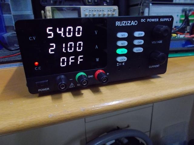 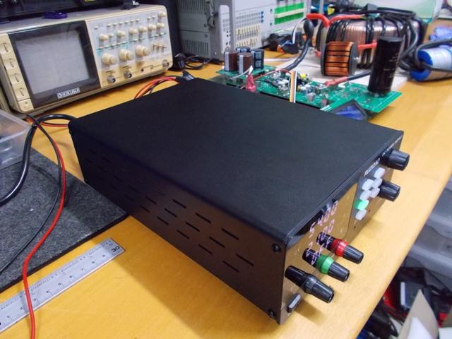 NANO:Inverter V 8.2ks - Linux AvrDude GUI script V4.1 |
||||
| wiseguy Guru Joined: 21/06/2018 Location: AustraliaPosts: 1297 |
I saw that power supply too and am considering buying one, I think it was around $360AUD from memory - thanks for bench testing it :). I would like to add some comments into the melting pot with regard to noise. The reason noise becomes an issue is often because a more sensitive node receives a signal relative to the non sensitive node of a functional block. There are methods to reduce the noise between them, one involves filtering out the noise on the sensitive input and often a simple RC filter is employed. This may cause an added undesirable attenuation to a fast response. In inverters and switchmode and other high speed switching circuits, placing a suitably sized ceramic capacitor strategically placed to couple the sensitive input to the non sensitive return node can result in coupling the very fast edges into what I call common mode, that is both nodes are now coupled together and move together for very fast edges resulting in no differential signal that can get amplified, but allowing normal behaviour to the signal of interest. With regard to the Nano controller, having a ground plane on the PCB helps enormously in trying to shield sensitive nodes from noise pick up. If a chassis is directly under the PCB separated by say 10mm or the controller is too close to the power switching end there can be capacitive coupling through the air to the sensitive node. The noise may be already present on the ground plane of the PCB (from the wiring to it), but slight capacitive coupling of the sensitive node to the chassis or other generated noise now has introduced the problem "difference signal". By having a metal shield or chassis plane under the controller and placing a multilayer capacitor ie 10nF from the ground plane of the controller to the chassis/shield plane is one method to try to ensure that any potential difference signals to sensitive node/s are reduced or eliminated. In the case of Revlac, placing the longish yellow wire to the chassis ground, the wire is effectively an inductor and the coupling between the ground plane and chassis for very fast edges is usually totally ineffective. That is why the extra ground-plane to mounting screw capacitor can help so much, with the spacer usually brass and ~ 10mm long and is very effective at low impedance coupling. It is possible that if you use a large enough conductor that has much less inductance associated with it then that apparently also has the right effect, there are lots of ways to herd cats. In the end I have chased and resolved many "noise" transient type issues in my career that have confounded engineers with far greater and wider knowledge bases than I have. Sometimes the solutions were found by just being tenacious enough to not give up. In the end the correct solution/s for any piece of hardware is the one that worked. A one size fits all solution can be unachievable and unrealistic and may involve different techniques. Lastly whilst on this subject I notice a number of LCD issues where they "go off into the weeds". I have seen no operation, strange language characters and gibberish on screens and had these issues with our own products, always on serial data comms to the LCD. The method I found most effective was to place a 10nF capacitor from the ground connection on the LCD PCB to one of the (6?) bent tabs retaining the LCD screen housing cover to PCB. This is also an instance of noise being injected into the electronics on the display PCB and in my experience usually generated from the LCD metal housing onto PCB traces. By coupling the metal housing to the LCD ground it removes this mode, I prefer to use a capacitor than wire link as if the LCD metal cover is ever in contact with the chassis it wont cause an unintended ground loop path. Just for interest one of the products was a battery charger for rail crossing use. As we could not afford to have a unit fail (failure was not an option). The rail engineers apparently weren't filled with confidence when the charger had a blank screen when they were doing routine checks. We went for a belts and braces approach. We put a pic controller on the LCD that converted from the serial string back to parallel data to the LCD. Then we could read back the status of the LCD display controller with the PIC and fix the issue with corrective commands. To test we would wrap the outer of the LCD/controller into a multiple coil winding and using a 12V source and a bastard file and a timber nail we would wipe the nail across the file creating a wonderful arcing sparking effect to test against induced noise and once we were still able to kill the LCD (it would not respond to commands) and the only cure then was a power recycle. So on a spare port pin we placed a series transistor to the LCD power and were ultimately able to do a power reset to make the damn thing work again. After that we never saw another failure. We went for the PIC controller solution despite being overkill as it would just retrofit into all the existing chargers in the field as a (simple...) LCD replacement. Edited 2025-05-19 14:36 by wiseguy If at first you dont succeed, I suggest you avoid sky diving.... Cheers Mike |
||||
| KeepIS Guru Joined: 13/10/2014 Location: AustraliaPosts: 2194 |
Thanks for the extra detail, hopefully that will make the relationship between the ground post and the capacitor make more sense to builders using your Nano Controller. Some of my solutions come from years long ago building RF power equipment. BTW It's great to see the Inverter Boards being successfully assembled and powered up. The PSU: For what it's worth, under the cover of the Power Supply, all IC and components have part numbers, most parts appear to be quality items. 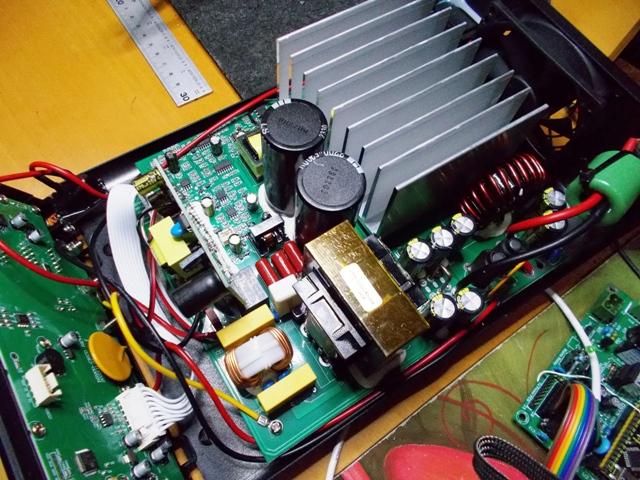 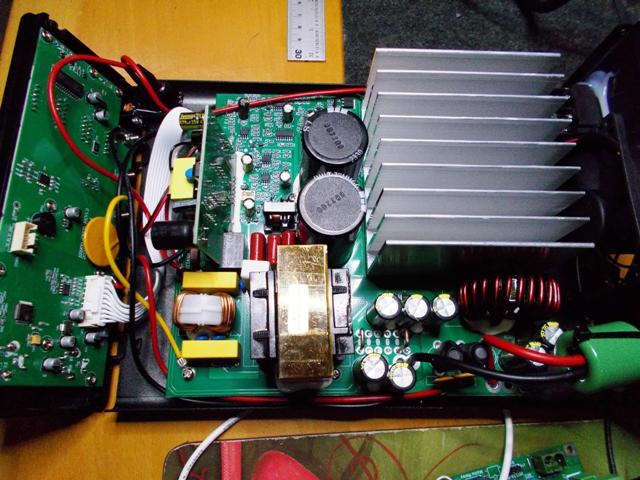 NANO:Inverter V 8.2ks - Linux AvrDude GUI script V4.1 |
||||
Revlac Guru Joined: 31/12/2016 Location: AustraliaPosts: 1282 |
Will try this on the Charge controller LCD.  The new power supply looks great  Footnote added 2025-05-20 19:54 by Revlac Just Checked some of these LCD's, one of them, its a green display LCD has all ready been grounded, metal case to the GND pin, it is 2004A V1.5, the other blue LCD's are not grounded....users would have have to check which version they have if grounded or not. Cheers Aaron Off The Grid |
||||
| KeepIS Guru Joined: 13/10/2014 Location: AustraliaPosts: 2194 |
That 10nF tip from wiseguy reminded me that sometimes we forget the LCD panel itself has a small processor which could also be corrupted by noise.  We were greeted with NO POWER when we woke up this morning, the last time this happened was almost two months ago - and I never found out why. We were greeted with NO POWER when we woke up this morning, the last time this happened was almost two months ago - and I never found out why.Anyway, it's always nice to see the Inverter still powered on when I open the door to the Shed - Status LED flashing over current. The Inverter LCD said an Over Current Trip had occurred and it needed a restart. FYI: In this dual inverter I have separate Trip indicators for Power-Stage-1 DC and AC trip and Power-Stage-2 DC and AC trip. Power Stage 2 AC Trip indicator was lit. Just means it fired first before PS 1. The AC Mains circuit breaker had then tripped when it auto-switched to Street Power. Where I have I seen this before? I reset the Breaker for Street Power AC, it didn't re-trip, restarted the inverter and all was good when it switched back to Inverter power. So once again something shorted out the AC at around 3AM (Graph monitor last record time stamp) There is no more than 250 Watts Load at that time. I'm again wondering if a Gecko tripped the power in one of the Air Conditioners or outdoor Power points. I powered up the Air Cons and fortunately they still work, a Gecko in the wrong spot kills them, I've had that before. It's been running for 4 hours and all is good, looks like another 2 month wait for the next time  On good thing, it's hard to kill this Inverter. From memory? (will have to check) each Toroids AC output is set to trip at around 15kW so 30kW total. NANO:Inverter V 8.2ks - Linux AvrDude GUI script V4.1 |
||||
| The Back Shed's forum code is written, and hosted, in Australia. | © JAQ Software 2026 |
