
|
|
Forum Index : Microcontroller and PC projects : Electronic heater plate....
| Author | Message | ||||
Quazee137 Guru Joined: 07/08/2016 Location: United StatesPosts: 603 |
As my Granddaughter hates this. But back in the day "early 1960's" My Dad and Grandfather had me help with this task. We use a big ZIPPO heater and metal cigar tubes wrap the egg with tissue then in the tube and into the ZIPPO bag. We'd get about 20 each time. The incubators for the chickens, ducks and pigons was gas powered.  |
||||
Grogster Admin Group Joined: 31/12/2012 Location: New ZealandPosts: 9932 |
@ Phil23: Trust you to actually research that comment.  "Clever girl." "Clever girl."@ redrok: I usually just provide a small-ish zone of insulated copper pour on top and bottom layers for heatsinks for these kind of parts. 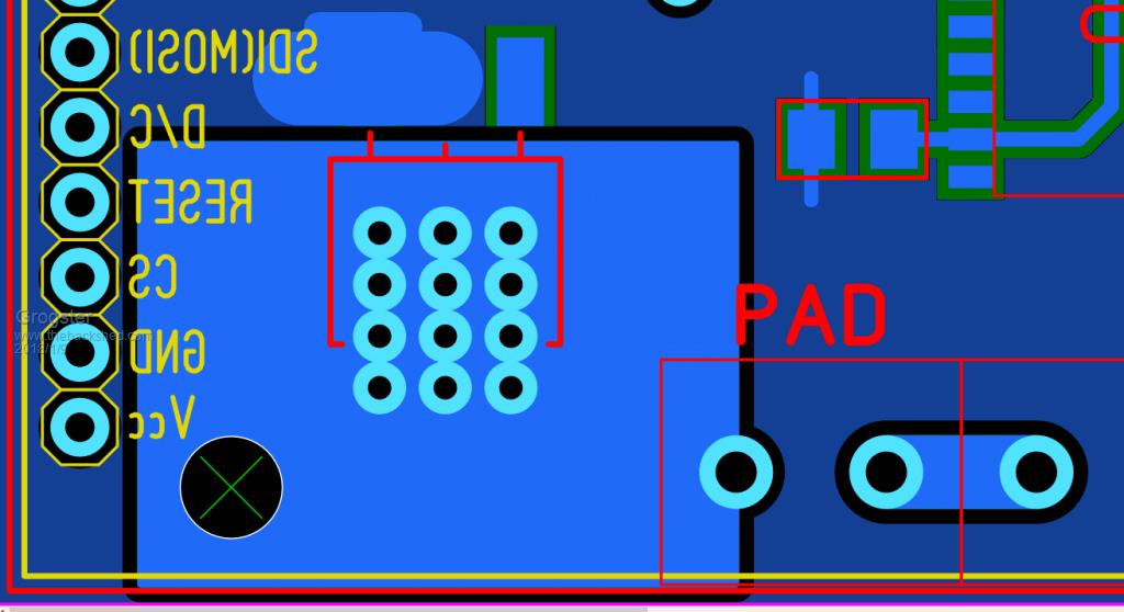 Thermal vias are filled with solder during assembly, but I doubt I would even need the bottom copper 'heatsink', but if you have room, why not allow for it.  I will add a 100k pulldown to the gate, and a 1k series. I will add a 100k pulldown to the gate, and a 1k series.@ Quazee137: Owwwww. Gas powered. Fried eggs. Smoke makes things work. When the smoke gets out, it stops! |
||||
| Quazee137 Guru Joined: 07/08/2016 Location: United StatesPosts: 603 |
It was small boiler much like an old peculator coffee pot. Hows the work going? |
||||
| Grogster Admin Group Joined: 31/12/2012 Location: New ZealandPosts: 9932 |
PCB's ordered, made, and on DHL to me now.(have arrived at Auckland Airport according to tracking) Waiting on heating pad to arrive. I got two. I will assemble the PCB while I wait. The PCB is designed as a backpack to a 2.8" SPI LCD with touch, so I can add some basic touch controls to the LCD screen. Old design used a red LED display, but the SPI LCD's can be setup however you want - including red 7-segment if I want it. Pad has NTC, but I have elected to use a couple of 18B20 temperature sensors, as they are much more accurate then a passive NTC would be. I have allowed for connection of the NTC to an ADC pin on the MM2 chip, just in case I elect to use it. I will post back to this thread as I progress with the project. Thank you for your interest.  Smoke makes things work. When the smoke gets out, it stops! |
||||
| grunto Newbie Joined: 07/01/2015 Location: AustraliaPosts: 15 |
A few thoughts (a bit late I know). Have no idea about bees but I have built a few incubator systems for birds (mostly parrots, although some chicken and quail systems). Learned some lessons along the way: 1. Make sure the incubator has good "thermal mass". This smooths out most of the temperature flucations (such as when you need to access inside the incubator) and makes the control system easier to design. I used to use plastic bottles full of water (3 or 4 x 1.25l soft drink bottles). 2. Use a forced air rather than a passive air system. Forced air eliminates hot and cold spots that tend to form in the incubator. I used a computer fan with a PWM speed controller and then used multiple temperature sensors (I think about 8) to ensure consistent temperature throughout the incubator. 3. Make sure it has an over temperature and under temperature alarm. Bird eggs were very sensitive to over temperature but less sensitive to under temperature (within reason). I also used a data logger for the temperature so I could compare temperature variations with hatch rates and this allowed the incubator temperature to be fine tuned. 4. 12V systems are a great idea - I often had to transport eggs in the incubator so being able to plug it into a car 12V outlet was very useful (although plenty of people I know just used a 240V inverter in their car). I just used a 12V power supply when I used the incubator at home. 5. Humidity control was often the hardest part - not sure if its is an issue with bees. High humidity was required leading up to hatching but measuring and adjusting humidity was always a challenge. I to make use of DHT22 sensors and used little 5V fans blowing across a shallow dish of water to adjust the humidity but the control loop was difficult due to the delay in generating a higher humidity. I was thinking that the little ultrasonic "fountain fogging" devices might be an alternative but never implemented such a system. 6. I tried many different heat sources - nichrome wire, light bulbs (and you can still buy incandescent bulbs in NZ I think), power resistors, peltier devices etc. I finally settled on in slab heating wire - I used it at 12V (it is normally 240VAC) and found a metre or so was about right (I used to just get "left overs" from new house builds - took me a while to learn that you can get it in different resistance / metre depending on the area being heated). 7. I use to keep my system in a the garage which was under the house - the temperature was pretty constant (compared to most rooms in the house, particularly during the day). Wife also preferred the system out of the house. Had a little display inside the house to monitor the system via a 433MHz link so i didn't have to go into the garage all the time - nowadays would probably just connect it to WiFi and write an app so I could use my phone..... After a few iterations the system was pretty robust and would run almost unattended for the full incubation period. Looking forward to hearing how you go. |
||||
| Grogster Admin Group Joined: 31/12/2012 Location: New ZealandPosts: 9932 |
Hi there grunto. Replies: 1) Original prototype(that sort-of worked) used a 3mm aluminium plate. I plan to make the new one 5mm at least, for the thermal mass you are talking about. I may even go thicker then that if the thicker plate is not prohibitively expensive. More mass. 2) Good idea, but not possible in this version as I have now built the new prototype PCB. Something to considder for another revised version if the new version does not work out though. 3) Something to add. Currently does not have any kind of audible alarm, just the LCD alerting. But if you are not looking at it..... 5) No, not an issue. They are surrounded by bees wax, inside a queen-bee carrier, which is then placed in the pillow(thick foam that sits on top of the plate, and is punched with a whole lot of holes so the carriers are a push-fit). They just need to be kept warm during transportation from the hive. Here are a couple of photos of the assembled unit: 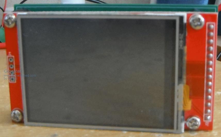 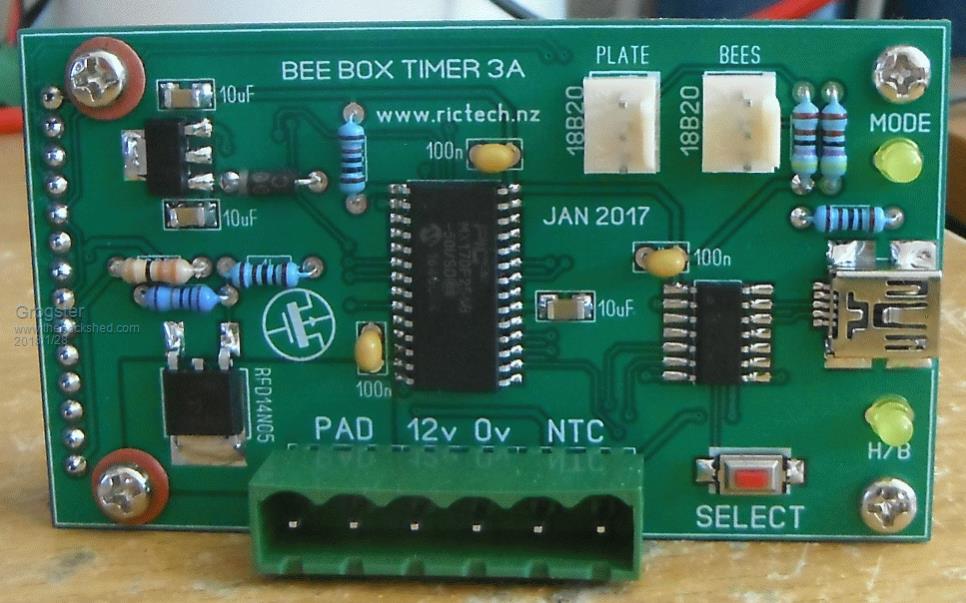 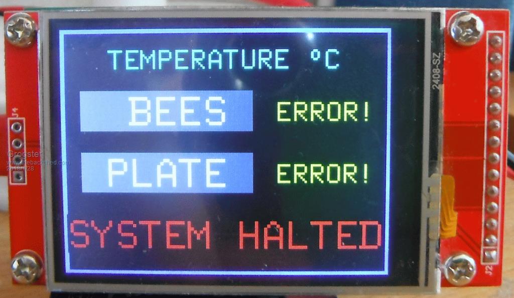 The last image is showing errors for the temperatures, cos I don't have any 18B20 sensors on it just yet, so the code is written to pick up on that and show an error message. The 'SYSTEM HALTED' message in red is actually blinking off and on. I will try to get some sensors on it later and post another image. Smoke makes things work. When the smoke gets out, it stops! |
||||
| Grogster Admin Group Joined: 31/12/2012 Location: New ZealandPosts: 9932 |
OK, I have hooked up a couple of 18B20 sensors, and this is what it looks like under normal operation: 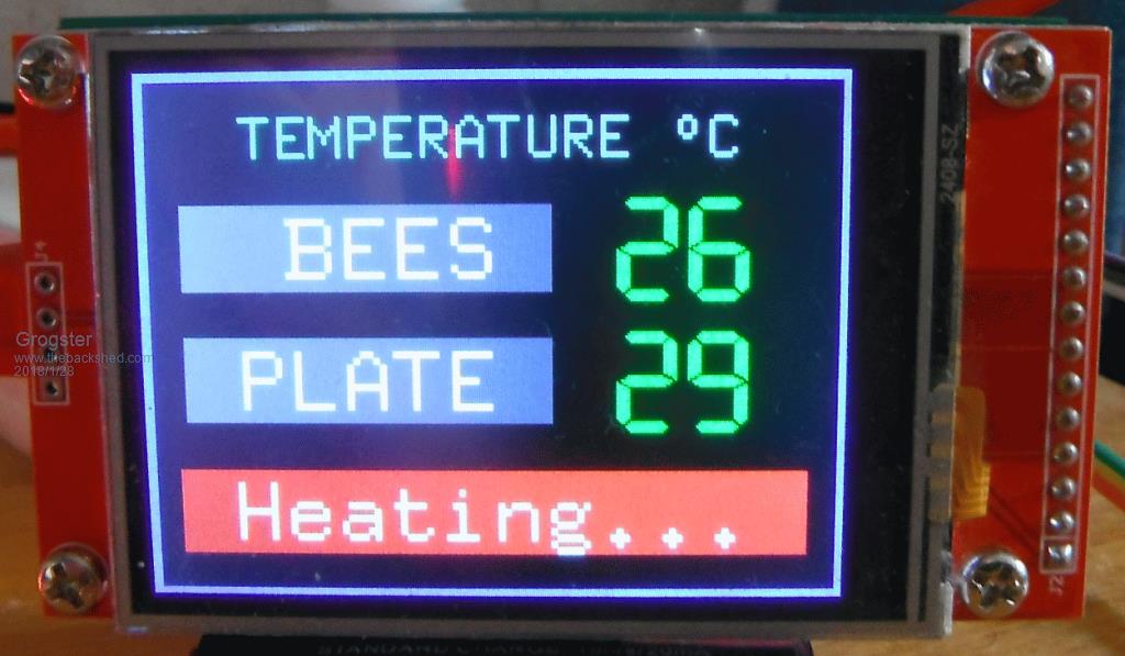 Smoke makes things work. When the smoke gets out, it stops! |
||||
| hotwater Senior Member Joined: 29/08/2017 Location: United StatesPosts: 120 |
delete |
||||
| twofingers Guru Joined: 02/06/2014 Location: GermanyPosts: 1732 |
Hi Grogster (Bee King) I would consider just to insert a 1l (aluminium-) bottle of water. About temperatures: What is the highest temperature in your country? What are the highest temperatures your bees can survive? EDIT: If the highest temperature you have to expect exceeds the bees maxima then you have maybe to consider a cooling e.g. peltier element.  Needless to say: I like your project! Just my 2c Michael causality ≠correlation ≠coincidence |
||||
| Warpspeed Guru Joined: 09/08/2007 Location: AustraliaPosts: 4406 |
I doubt if bees could survive out in the wild if the day temperature exceeded what they could tolerate. I still think that a large finned aluminium heatsink and a bolted on resistor would be the simplest way to have high thermal mass, with very good thermal coupling to the air. 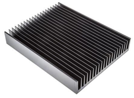 Cheers, Tony. |
||||
| Grogster Admin Group Joined: 31/12/2012 Location: New ZealandPosts: 9932 |
@ hotwater: Why 'delete'? @ warpspeed: I am reasonably confident the heating pad will do the job well, but lets assume not, and if I used your finned heatsink idea, how many resistors would YOU be inclined to use? ...and their value + rating in W..... I'm just keeping my options open. Smoke makes things work. When the smoke gets out, it stops! |
||||
| Warpspeed Guru Joined: 09/08/2007 Location: AustraliaPosts: 4406 |
Look up metal clad resistor on e-bay. You can get any resistance value, and over a wide range of physical sizes. Just one resistor would work fine, the heat will spread pretty evenly over the heatsink. Two or three smaller resistors may be mechanically easier, but the heat should be pretty even only with one resistor. 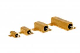 First thing is to determine how much power you need. Suppose you assume a 40C incubator temperature, and the lowest outside ambient of say 10C. We need enough power to keep the inside 30C hotter than the outside in this example. Yesterday it was stinking hot, 40C here in Melbourne, but we could still test our incubator by finding how many watts are needed to keep the inside 30c hotter than the outside. Say 70C for the test if its 40c ambient. So we need "something" inside to generate some test heat. Maybe some 12v light globes, or whatever odd selection of resistors you can scrape up. Get an adjustable dc power supply and feed in some power. We only need to find out the relationship of inside temperature rise to the watts we are feeding in. Leave it overnight to reach a stable equilibrium. Your first guess may be way out, so try raising or lowering the power to get some sort of reasonable temperature rise. When you know roughly how many watts are needed, you can then work out the required resistance with whatever battery voltage you decide to use. Choose a resistor of much higher rated wattage so its not running flat out, but select the resistance value for the actual power required, plus a slightly more so it will heat up to final temperature a bit faster. I would not place the eggs/bees or whatever, directly on top of the heatsink but on something like very fine wire mesh (flywire ?) that would allow a very free air circulation around both eggs and heatsink, even without a fan. Cheers, Tony. |
||||
| isochronic Guru Joined: 21/01/2012 Location: AustraliaPosts: 689 |
I have been told 45 deg C is ok for bees, in fact they will survive 56 deg for a short time (15 min) and it makes varana mites drop off. Don't know how reliable it is though. Ed the small native bees prefer the heat I think, not a commercial honey source though. |
||||
| Warpspeed Guru Joined: 09/08/2007 Location: AustraliaPosts: 4406 |
I have a native bee hive in my garden. They took over what was supposed to be a possum box, they have been there for a couple of years. Cheers, Tony. |
||||
| Grogster Admin Group Joined: 31/12/2012 Location: New ZealandPosts: 9932 |
The heating pads have arrived. They are a nice looking unit, and seem very solid. Current @ 12.0v is 3.2A Heating is slow, but very even across the entire pad, width and length. I'm pretty pleased with these things so far. MOSFET get's warm, but not hot. Smoke makes things work. When the smoke gets out, it stops! |
||||
redrok Senior Member Joined: 15/09/2014 Location: United StatesPosts: 209 |
Hi Grogster;There is a ThetaJA, Junction to Ambient, speck for the RFD14N05 which is 80°C/W free air and ThetaJC, Junction to Case, 3.125°C/W heat sinked. My measurements of the RFD14N05 with a 3.3V gate drive is 64mΩ, (here is the graph). 3.2A^2 * 64mΩ = 0.66W Assuming the MOSFET is on 100% .66W * 80°C/W = 52°Cdelta rise above ambient free air no heat sink or .66W * 3.125°C/W = 2°Cdelta rise above ambient with heat sink Adding in your ambient temperature: 52°Cdelta + 35°CAmb = 87°CJunc free air or 52°Cdelta + 2°CAmb = 54°CJunc heat sinked Not to hot as the parts junction is rated for a Tj of 175°C BTW you could use the heater plate as the heat sink. redrok |
||||
| Grogster Admin Group Joined: 31/12/2012 Location: New ZealandPosts: 9932 |
redrok, the king of the calculations, returns! Cheers for that. If you look back on this thread, you will see a photo I posted of the small PCB zone I am using for the MOSFET heatsink. This seems to be coping just fine. As I say, it gets warm to the touch, but not hot, so I think that also armed with your mathematics, we are well within spec. I have ordered some 8mm aluminium plates that suit the size of the heating pads, plus 20mm to give me room to actually route the pad wires without having to bend them at 90 degrees to get it in there if you see what I mean. 8mm plate was the thickest I could get from my favourite engineering works, but I expect that should work well in terms of thermal mass. That is thicker then the original plate(3mm), and the pad should ensure the plate will heat up evenly. I will post photos as I go. Smoke makes things work. When the smoke gets out, it stops! |
||||
| redrok Senior Member Joined: 15/09/2014 Location: United StatesPosts: 209 |
Hi Grogster;Ya, I forgot about your image.Aluminum may not be the best material for your purpose. 1. You don't need heat spreading as this is already done for you by the rubber heater. 2. You want maximum thermal mass for a given weight. Polypropylene plastic has far more thermal mass than aluminum. Basically how much heat per weight of material. Also called specific heat capacity. This chart shows aluminum at 0.897J/(g°K) whereas Polypropylene is 2.3027J/(g°K). So polypropylene is over 2.5 times better than aluminum for the weight. Just saying! Have fun redrok |
||||
| Grogster Admin Group Joined: 31/12/2012 Location: New ZealandPosts: 9932 |
Are you saying to use a PLASTIC heating plate rather then aluminium?!?!  Plastic cannot conduct heat better then metal, surely.....if that's what you are saying....  Smoke makes things work. When the smoke gets out, it stops! |
||||
| redrok Senior Member Joined: 15/09/2014 Location: United StatesPosts: 209 |
Hi Grogster;I'm not saying it conducts better, it doesn't have to, I'm saying it has better thermal mass, weighs less, and is cheaper. More math: Material density or specific Weight of Polypropylene = 0.855g/cm3. Aluminium = 2.375g/cm3. Assuming the plate areas are the same we'll only compare thickness. The relative specific weights are: AL / PP = 2.375g/mm 0.855g/mm = 2.778RSW Relative Specific Weight and The Relative Specific Heat is: PP / AL = 2.3027J/(g°K) / 0.897J/(g°K) = 2.567RSH Relative Specific Heat Assuming the 8mm AL is the standard for "Specific Heat" then the PP with the same specific heat would be: 2.567RSH / 2.778RSW * 8mmAL = 7.4mmPP Yeh, for the same thermal mass PP is thinner. PP has a slight advantage over AL, about 10% better thermal mass. I also suspect PP is much cheaper than AL and weighs about 1/3 as much. Now if you triple the thickness to 22mm of PP it would have 3 times as much thermal mass and weigh about the same as 8mm of AL. Thermal conductivity is of "Nearly No Concern" because the heat is passing strait through 7.4mm, not laterally where AL would have an advantage. There are other plastics that are better than PP but you get the idea. I couldn't find epoxy fiberglass which may be even better. I hope I did that right. Have fun! redrok |
||||
| The Back Shed's forum code is written, and hosted, in Australia. | © JAQ Software 2026 |
