
|
|
Forum Index : Microcontroller and PC projects : Explore-64 version 1D....
| Author | Message | ||||
Grogster Admin Group Joined: 31/12/2012 Location: New ZealandPosts: 9975 |
OK then, I will route Vbus somehow. This does allow for the MM+ to perhaps host a USB keyboard on it's USB socket, if that was ever added. The only problem I now see, is that someone could solder-blob those pads AND install a daughter-board. That would be bad, so perhaps I should remove those solder-blob pads? Smoke makes things work. When the smoke gets out, it stops! |
||||
| WhiteWizzard Guru Joined: 05/04/2013 Location: United KingdomPosts: 2991 |
Thanks again Peter. In that case I would propose that Grogster's three pairs of solder pads is a great solution. Only in extreme cases where you need to recover code in an OPTION CONSOLE OFF scenario would you need to get out a soldering iron. For users wanting to use USB (and not the daughter board) then simply solder bridge these; you then have an 'existing' E64 Best of all, the new E64 doesn't look scary at all to a 'new user' Win-win all round IMHO Great 'global' input in helping Grogster tweak his new E64  |
||||
| Grogster Admin Group Joined: 31/12/2012 Location: New ZealandPosts: 9975 |
I do appreciate all the comments on this thread. Thanks everyone.  How about my comment on having the solder-blobs in place, and then you install the daughter-board - this will then connect the PIC32 USB directly to the 1455 USB, which would not be a good thing. Apart from the fact that the USB bus would probably get really confused, is there any ELECTRICAL risk if that happened? IE: Would doing that damage one or the other chip, or will it just prevent any USB working on that port till you isolate one or the other? Smoke makes things work. When the smoke gets out, it stops! |
||||
| WhiteWizzard Guru Joined: 05/04/2013 Location: United KingdomPosts: 2991 |
@Peter, I fully appreciate about a parallel USB connection but what are your thoughts with the following: D+ and D- from the E64 USB socket being wired to the MM PIC (but MM Vusb not connected) AND D+ and D- from same E64 USB socket also goes to 'MicroBridge' PIC Will the MicroBridge/PC communicate correctly, or will the MM PIC (D+/D-) somehow 'interfere' with the MicroBridge comms? |
||||
| matherp Guru Joined: 11/12/2012 Location: United KingdomPosts: 11513 |
No way of knowing but definitely not sensible design |
||||
| robert.rozee Guru Joined: 31/12/2012 Location: New ZealandPosts: 2528 |
if you are fitting a 1455, why not keep two seperate USB sockets, with the daughterboard carrying the second socket? they could end up sitting one vertically above the other. remember, there is the USB OTG pin of the onboard USB socket routed to a pin on the PIC32. it may be possible to use this as a means of either (a) detecting if the daughterboard is attached, or, (b) overriding OPTION CONSOLE OFF i could be way off the mark here, having never seen or used an E-64, and not having looked at the schematic. i just remember asking that the OTG pin be routed to what i recall was an input-only pin on the PIC32, and folks agreeing that it was a good idea. cheers, rob :-) |
||||
Azure Guru Joined: 09/11/2017 Location: AustraliaPosts: 446 |
I checked the PIC32 Reference Manual: VUSB should always be connected to 3.3V it drives the internal USB transceivers. VBUS should be connected to the USB connector power pin as it is used to monitor the voltage at the USB connector. I will defer to Peter on this as it may not be correct and I have not checked the MM source, but I have thoroughly read the PIC32 USB implementation reference. A change in the voltage at VBUS can cause an interrupt. It should not cause any interrupts if it is stable (which it should be being it is the power pin). It should not cause any processing overhead after initialisation if the data pins are not doing anything. I checked the E64, E100 and SC MM+64 BP circuits and VBUS is always connected even if the connector is only used as the power not data. |
||||
| WhiteWizzard Guru Joined: 05/04/2013 Location: United KingdomPosts: 2991 |
My understanding was that Vbus disabled the D+ and D- lines at both a hardware and a software level (when not connected to +v). When a voltage is detected then it enables USB D+ / D- on the PIC. I will investigate / experiment later today as now have to go out . . . . |
||||
| matherp Guru Joined: 11/12/2012 Location: United KingdomPosts: 11513 |
On many PIC32 VUSB can be connected to GND to disable USB. Saves a small amount of power. However, the MX470 datasheet implies it must always be connected to 3.3V PIC32MZ PIC32MX470 |
||||
| WhiteWizzard Guru Joined: 05/04/2013 Location: United KingdomPosts: 2991 |
Oh - seems a bit weird as according to that data sheet (for MX470), then Vusb must be high at all times? So how does the PIC (not the MM firmware) know the difference between whether the USB is inserted or not? Does that mean the PIC monitors D+ / D- all the time on that basis?  Or perhaps the data sheet should read Or perhaps the data sheet should read '...must be connected to Vss' (surely MicroChip never make errors like this!  ) )I don't want this matter to distract from the main concept - just trying to minimise number of jumpers/solder-blobs. So seems like two pairs of solder pads (D+ & D-) will meet E64 requirements with it being the responsibility of the end-user not to short out the two solder-pads AND also use daughter-board at the same time. |
||||
| Azure Guru Joined: 09/11/2017 Location: AustraliaPosts: 446 |
I have just been through the MM source (albeit a lot of skim reading) and unless I have missed somethinh I have not been able to find anywhere the USB VBUS input is actively monitored. I think it is worth checking further as it will solve whether it is OK to connect permanently or not. I may have to be corrected on this, but I do not think it should be left disconnected. My logic is it can be powered by a USB power cable with no Data, VBUS would get power and D+/D- could potentially not be connected to anything. Same applies if powered externally and jumper is left in but no USB connected. I'll try that in a few minutes. I could check it more thoroughly if I can find an easy way to isolate the USB power pin or VBUS to the MM+ and ramp it from 0v to 5v on a lab supply while connected to a USB console and doing comms. I can remove the normal USB/Ext jumper to power it seperately but I also need to isolate the USB host power coming in from the PC. I might be able to cannibalise a USB cable or lift the power pin on the USB socket. I'll see what I can manage tomorrow morning. Edit: (small steps) My SC MM+BP can be powered externally with the USB jumper being plugged in and removed multiple times while running a program (which communicates with the console through the serial port) and it works fine without any hiccups. So that has VBUS powered and no connection on D+/D-. |
||||
| Azure Guru Joined: 09/11/2017 Location: AustraliaPosts: 446 |
@Matherp and WhiteWizzard. MX470 requires VUSB connected to 3.3V at all times as it drives the transceivers, with no power the inputs would be in a strange state and possibly create an unwanted current sink or source through a D+/D- signal. These can be shut down in software for low power mode if not being used. VBUS is the questionable pin as it monitors the USB power signal. It monitors the connected USB port power (analogue input) so the software can react if the voltage is not correct (supposedly but lets not go there). |
||||
| matherp Guru Joined: 11/12/2012 Location: United KingdomPosts: 11513 |
You have  void CheckUSB(void) { int i; static int USB5V = 0; if(U1OTGSTAT & 1) { // is there 5V on the USB? |
||||
| Azure Guru Joined: 09/11/2017 Location: AustraliaPosts: 446 |
Thanks Peter, it did not make sense that I could not find a reference to it. I will try the second test I suggested to confirm that to use the USB console VBUS must be connected to an acceptable (USB 5v) rail. |
||||
| Grogster Admin Group Joined: 31/12/2012 Location: New ZealandPosts: 9975 |
In the 1B's and 1C's, if you plug in the USB cable, Pin-34 is connected to the 5v USB voltage. I have run E64's with the plug in, and the motherboards that use the E64 module as the 'CPU' do NOT have the USB cable connected - they are powered directly from the 5v pin on the module, with J1 removed(USB 5v NOT routed through to regulator) On all E64's, Pin-35 of the QFP(Vusb3v3) is ALWAYS connected to Vdd(3v3). It is ONLY pin-34 of the QFP(Vbus) that is connected or disconnected via the USB cable and socket. This has not changed, and won't. It is only Vbus(pin-34 of the PIC32) that we need to worry about. Smoke makes things work. When the smoke gets out, it stops! |
||||
| WhiteWizzard Guru Joined: 05/04/2013 Location: United KingdomPosts: 2991 |
 This confusion has possibly been brought about by me This confusion has possibly been brought about by me I was referring to Pin 34 but kept calling it Vusb (instead of Vbus). Lets just put it down to 'pressing the keys in the wrong order' mistake maybe!!! Will soon be trying the computer's D+/D- connected to MM PIC (with Vbus not connected), and a MicroBridge connected simultaneously to see if the MicroBridge functions as required. Sorry for the confusion |
||||
| Azure Guru Joined: 09/11/2017 Location: AustraliaPosts: 446 |
I did some checking today (and it took me down a rabbit hole that I have not gotten out of yet). Just for reference the 1455 does not use VBUS - thank goodness for that. I have figured out how I isolate the USB Power pin so I can independantly change VBUS on one of my SC EXP100 boards. I will just trash a SMD USB connector, that I have plenty of. That will let me try all of the combinations of scenarious which I have put together in a spreadsheet. Ran out of time to do it today, hopefully tomorrow morning. With the shorting blocks, one limitation will be you cannot have them shorted and connect the 1455. |
||||
TassyJim Guru Joined: 07/08/2011 Location: AustraliaPosts: 6538 |
I made a "veroboard special" microbridge. 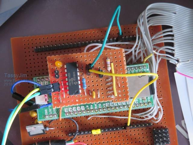 I did add a 0.1uF capacitor to the power rails (out of habit). I also have terminals so I can re-flash the pic if needed. It works on my explore64 but I have to re-visit the USB side. I have a fault in the butchered wiring so I am using a separate USB cable direct to the microbridge. Jim VK7JH MMedit |
||||
| Grogster Admin Group Joined: 31/12/2012 Location: New ZealandPosts: 9975 |
Clever! The USB D+ and D- must have been tricky to get at....The new 1D's have been ordered. This is the 1A prototype run, so I have only got ten of each, just so I can check that everything still works as expected. If that is OK, then I will get panels of three made for the new design, and I will also put up the new design and optional USB board on the website. 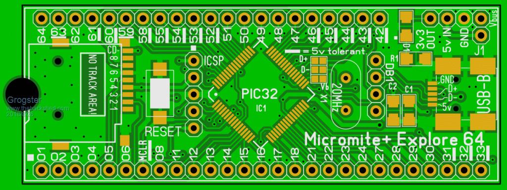  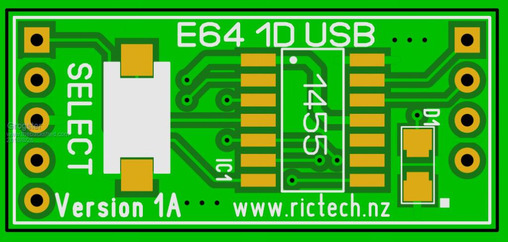  The new boards are blue. Weather I move back to green for the production boards remains to be decided, but I was getting sick of all my boards being green, and PCB GoGo don't charge any extra for a different colour soldermask. It used to cost quite a bit more to get any other colour then green, but like everything, that has changed now. Smoke makes things work. When the smoke gets out, it stops! |
||||
| Azure Guru Joined: 09/11/2017 Location: AustraliaPosts: 446 |
Great that you managed to squeeze in the VBus pad as well. Solves any potential USB issues. Even if it works now that could change in a future version if MM USB code is changed. |
||||
| The Back Shed's forum code is written, and hosted, in Australia. | © JAQ Software 2026 |
