
|
|
Forum Index : Microcontroller and PC projects : Water Level meter - How to sleep mode
| Author | Message | ||||
| Turbo46 Guru Joined: 24/12/2017 Location: AustraliaPosts: 1693 |
A capacitor at the base of the transistor may stop the pulses affecting the FET but not the cause. I suspect that the pulses are caused by instability as you suggested earlier. Looking at some circuits on the web I noticed that some use a 100uF tantalum capacitor across the supply. That may help with the stability problems. Jaycar have 47uF tantalums (I buy them for the Micromite) you could try tacking one (or two) across the supply pins on the back of the processor chip. The 470uF capacitor across the incoming supply may help as well. Removing the pull-down 4K7 resistor may help a little by reducing the load on the processor a tiny bit. Bill Keep safe. Live long and prosper. |
||||
TassyJim Guru Joined: 07/08/2011 Location: AustraliaPosts: 6538 |
I know little about Arduinos either but I agree with Bill, decent capacitor on the power supply as well as a 0.1uF for HF suppression. To negate the short pulses I would use something like this: 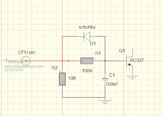 Having a capacitor directly connected to the CPU pin only overloads the CPU and wouldn't do much for spike reduction. It would draw a lot of power unnecessarily. R1 C1 do the filtering. I haven't looked at the timing of your spikes but I would uses 100k and 0.1uF as starting points. R2 is there if the CPU pin goes high Z when in sleep mode. The diode discharges the capacitor quickly when the CPU pin goes low. Schottky is needed to get the voltage below the transistor torn on level. You may not need any diode. This should stop the short spikes turning the transistor on but I would not be comfortable putting the system into service until I know the cause of the spikes. Jim VK7JH MMedit |
||||
| robert.rozee Guru Joined: 31/12/2012 Location: New ZealandPosts: 2528 |
hi, try removing the 47uF filter capacitor from the HC-12, and instead place it at the supply feed into the MOSFET (Q5). the on resistance of the mosfet will be minimal, so the capacitor will still have the desire effect wrt filtering the supply to the HC-12. i suspect what is happening is that when the MOSFET starts to turn on, charging of the 47uF capacitor pulls down the V+IN supply. this is interfering with the drive to the gate of the MOSFET, causing it to turn off a little, allowing the V+IN supply to increase again... giving the oscillation you're seeing. just a theory. cheers, rob :-) |
||||
| erbp Senior Member Joined: 03/05/2016 Location: AustraliaPosts: 195 |
I also know nothing about Arduinos, but here are a couple of suggestions. 1. It seems strange that the spikes you see on DP5 occur BEFORE DP5 switches high. So do you know the timing of when the CPU switches DP5 high compared to when it actually stabliizes at the high level? In other words does the CPU attempt to switch DP5 high at the START of the spikes (or the low level rise when you have the 470uF connected), but something internal or external is delaying the pin from actually rising to the stable high value? Maybe you can set a spare pin as a digital output and turn it high immediately prior to turning DP5 high. You could then compare the timing on the spare pin with what you see on the scope on DP5. 2. What does the waveform on DP5 look like if you disconnect it from the resistor, capacitor and base of Q10 - i.e. with it unconnected? Does it still show the spikes, and can you also determine the relative timing with relation to suggestion 1 above? 3. What happens if you disconnect the HC12 and SR-04 modules and just use a 1K or 470R resistor from the Drain of the Q5 MOSFET to ground to provide a token load? Are the spikes on DP5 and instability on the output of the MOSFET still evident? I'm not sure if any of these will reveal anything, but they are the things I would be doing to try to get a handle on what is causing the instability. Cheers, Phil. |
||||
| Turbo46 Guru Joined: 24/12/2017 Location: AustraliaPosts: 1693 |
Hi yet again Timbergetter, There a couple of good points above: Are the pulses before the DP5 is actually switched? Or are they an effect of trying to charge the 47uF capacitor via the FET 'glitching' the supply? Have you taken a trace of the power supply rail while this is happening? If you have put the 470uF capacitor across the supply that will reduce that a bit and mean that you could probably remove the 47uF capacitor altogether. If you have replaced the base resistor with 100k and removed the capacitor then nothing should be fed back into DP5. I would still include a tantalum across the power supply pins of the chip. Bill Keep safe. Live long and prosper. |
||||
Timbergetter Regular Member Joined: 08/10/2018 Location: AustraliaPosts: 57 |
I am so grateful for all you guys putting so much time and thought into solving my problem. There has been a strange new dimension arrive on the scene out of left field. I now have two versions of the device. One exhibits the pulsing problem and the other doesn’t. The one that seems to be working perfectly is the breadboard with its tangle of jumper leads. The one that stubbornly persists with the pulse problem is on a carefully fabricated PCB, albeit one that has been diy etched. I have migrated nearly all components back and forth between the two board platforms. The only components I haven’t touched so far has been the two 22 pf caps. I am using the same HC-12 radio and ultrasonic sensor on both platforms. I even have the MosFet and its associated components on a moveable daughter board so that is verified at the module level. No matter what I have tried the problem remains with the PCB. My plan now is to strip the PCB of all components and try to test for parasitic impedances between tracks. Visually the board looks ok. I am quite embarrassed by all the support I have received at BackShed only to arrive at this point. I’ll report back when I have discovered the root cause. |
||||
| Turbo46 Guru Joined: 24/12/2017 Location: AustraliaPosts: 1693 |
Have you tried the suggestions above? Rob's with the 47uF capacitor and Phil's re the timing of the DP5 output? Are the pulses happening BEFORE the DP5 output is SUPPOSED to go high? Taken a trace of the power supply at the time of the pulses? Bill Keep safe. Live long and prosper. |
||||
| Timbergetter Regular Member Joined: 08/10/2018 Location: AustraliaPosts: 57 |
Moving the 47 µF cap from the HC-12 supply to the supply feed to the MosFet did reduce the number of pulses from 10 to between 2 and 3 but did not eliminate the pulses nor reduce their amplitude. Traces-04a 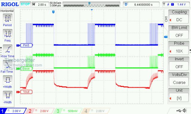 This trace shows two and bit cycles of the device waking, sending readings then going into sleep mode. I think you can see that the commencement of pulses is synchronous with duty triggered by the sketch. (Note that I have changed the sketch so that it is now sending 10 packets of data during each wake cycle, thus the 10 blips on the traces during the wake period) Traces-04 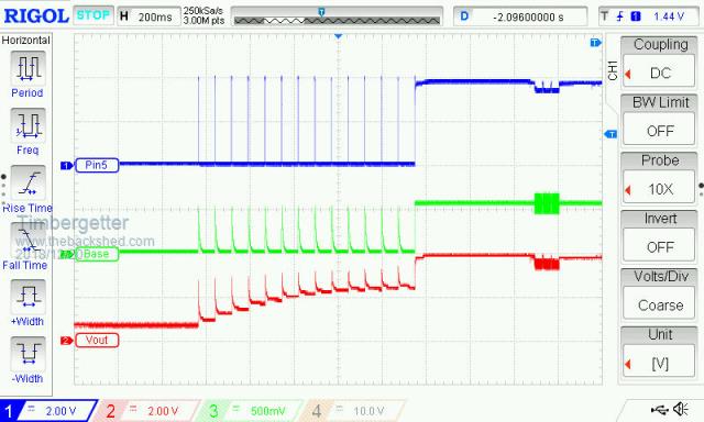 This shows 13 pulses on DP5 before the MosFet turns on. The MosFet output (Vout) is pulsing in sympathy with the DP5 pulses with its voltage ramping upwards as it advances from pulse to pulse. Traces-05 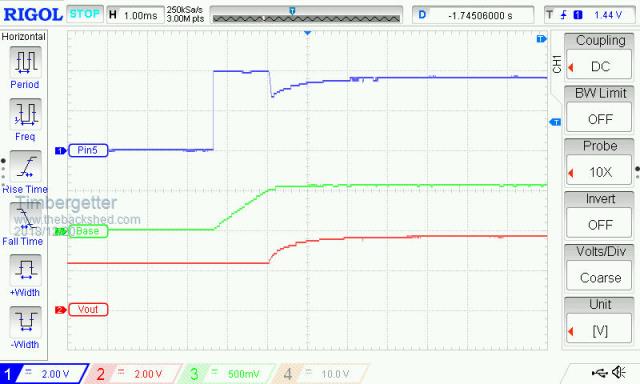 This trace zooms in at the time when the MosFet turns fully on. Trace-06 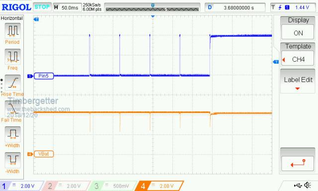 For this trace I powered the device from battery. It shows negative pulses on the supply line from the battery in sympathy with the pulses on DP5. (Powering the device with my el cheapo bench supply gives a similar result). Trace-07 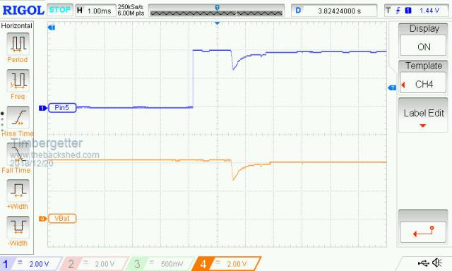 This trace zooms in at the point where DP5 finally stays high. As I said in my earlier post all these problems are on the PCB version of the project. My breadboard version has no pulses evident until the supply voltage drops below about 3.3 volts. I am now preparing to tear down the PCB and check for parasitic impedances on adjacent tracks. |
||||
| Turbo46 Guru Joined: 24/12/2017 Location: AustraliaPosts: 1693 |
I feel your frustration. I still think Rob's suggestion is close to the mark. There does seem to be some 'motor boating' going on. It looks like the supply is dipping to nearly 2 volts if I am reading your trace correctly. That may be causing the DP5 output to drop too low and turn the transistor off and therefore the FET thus reducing the load on the power supply allowing the voltage rise again and so allowing the DP5 output to rise again. This dipping of the supply is probably causing the processor to eventually lock up. If your circuit is correct and checked with a multimeter I would try more capacitance on the supply. Maybe heavier wiring to the supply? Bill Keep safe. Live long and prosper. |
||||
| Turbo46 Guru Joined: 24/12/2017 Location: AustraliaPosts: 1693 |
Hi Timbergetter, Please have a look here to see what Grogster says about the HC12 and power supplies. Bill Keep safe. Live long and prosper. |
||||
| Timbergetter Regular Member Joined: 08/10/2018 Location: AustraliaPosts: 57 |
I decided against stripping down the PCB looking for elusive impedances. Instead I have tried to implement the consensus proposals of Bill, Jim and Phil. So far it appears to have totally succeeded. This is the trace I am now getting: 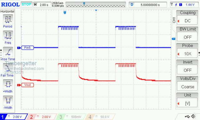 The trace is for a supply voltage of 3.5 volts. The pulses start to appear for a lower supply voltage and / or for values of C7 below 220 µF. I am now solidly in the domain of battery operation (3 x AA alkalines and a sleep current of less than 6 micro amps). The schematic around the MosFet switch now looks like this: 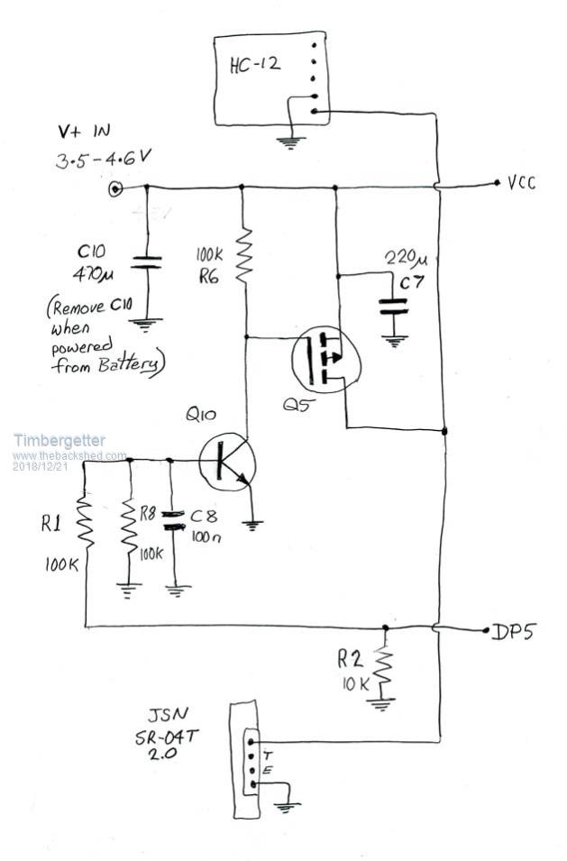 Moving C7 away from the drain side of the MosFet seems to have had the biggest effect. R8 is probably redundant now, but I’ve left it in. The device appears to be sufficiently robust now to deploy and to focus on the receiver end of the system. I am so grateful for you guys who have helped me move this project along. |
||||
| Turbo46 Guru Joined: 24/12/2017 Location: AustraliaPosts: 1693 |
Great news! Thanks for sharing - we all learn from other peoples problems. Grogster said in another post: Maybe that caused it to draw extra current and make things worse. Bill Keep safe. Live long and prosper. |
||||
| CaptainBoing Guru Joined: 07/09/2016 Location: United KingdomPosts: 2171 |
great thread.  I still wanna know why that is not a clean HI... if you stretch the pulse on D5, does the "ringing" continue (i.e. is it a feature of that hi)? with everything disconnected from D5? bugging me... |
||||
| Timbergetter Regular Member Joined: 08/10/2018 Location: AustraliaPosts: 57 |
Hello Captain. I am sorry I didn’t notice the edit to your post till now. You are wondering what is responsible for the pulses observed while D5 is ostensibly held high. During each cycle of D5 high I am writing 27 packets out to the HC-12 radio. For the purpose of illustration I have temporarily inserted a 500 ms delay after each packet sent. I think this makes it clear that these packets are the culprits causing the observed effect on D5, as seen on the attached traces. The mpu and the HC-12 are both supplied directly from the battery so I am guessing that what we see is the voltage drop in the battery’s internal resistance each time the radio is used. The pulses I was getting previously, and which seemed to be leading to instability, were distinguished by ranging between 0 volts and supply voltage. 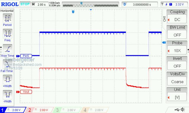 |
||||
| The Back Shed's forum code is written, and hosted, in Australia. | © JAQ Software 2026 |
