
|
|
Forum Index : Microcontroller and PC projects : Thinking about a new Pico PCB design for integrating into a keyboard
| Author | Message | ||||
| Mixtel90 Guru Joined: 05/10/2019 Location: United KingdomPosts: 8911 |
The only problem if you mount it flat is that you lose access to the USB connector. There are two ways round this: Cut a notch in the PCB and mount the Pico up to that end, allowing a USB plug to be plugged in or, and this is better, put THP pads in the appropriate places on the board and, when you are mounting the Pico, give it a dose of flux first then just fill the pad with solder. It will wick through to the Pico pad. Mick Zilog Inside! nascom.info for Nascom & Gemini Preliminary MMBasic docs & my PCB designs |
||||
| Tinine Guru Joined: 30/03/2016 Location: United KingdomPosts: 1646 |
How about a flying lead for USB, like the proposed VGA? I detest the micro USB  Craig |
||||
| Mixtel90 Guru Joined: 05/10/2019 Location: United KingdomPosts: 8911 |
You can't get a microUSB plug into a surface-mounted Pico. The plug wall is thicker than the PCB thickness of the Pico so it prevents the board sitting flat. You *might* be able to get flying leads off the bottom of the Pico and out through a big hole, but you're soldering onto SMD pads - you may as well put THP pads there and route the traces out to a USB connector of your choice. Why even consider flying leads? If the Pico is surface mounted the maximum height for the board is 15mm in total - and that's for the PS/2 connector so you may be able to do away with it. A VGA connector would give a maximum height of 14mm. The board profile would be naturally tapered inwards, especially if resistors aren't stood on end. I can get about 11mm-12mm height under a cheap keyboard at the back with the legs down. I could probably stick a 2" deep x a foot long pcb under it and still get all the connectors along the back simply by standing the keyboard on a 5mm spacing strip at each end. Another approach which I've not seen mentioned is to let the connectors stick out of the back of the keyboard. That would add about 22mm to the keyboard front-to-back measurement. The rest of the pcb would fit under the keyboard if it's kept more or less flat. I, personally, wouldn't want flying leads at all, preferably not special leads either as someone won't be able to make them. Mick Zilog Inside! nascom.info for Nascom & Gemini Preliminary MMBasic docs & my PCB designs |
||||
| al18 Senior Member Joined: 06/07/2019 Location: United StatesPosts: 238 |
The microUSB connector slightly protrudes from the Pico PCB. If the mating PCB edge lines up flush with the Pico PCB, you absolutely can plug in a microUSB cable into the Pico. |
||||
| Mixtel90 Guru Joined: 05/10/2019 Location: United KingdomPosts: 8911 |
Oh yes, if you can arrange it to line up that's fine, but I suspect people will want rear connection to the USB port for updates etc., so the Pico has to be arranged either front-to-back or the USB signals have to pass through 90 degrees to get to a socket on the back. Mick Zilog Inside! nascom.info for Nascom & Gemini Preliminary MMBasic docs & my PCB designs |
||||
| phil99 Guru Joined: 11/02/2018 Location: AustraliaPosts: 3291 |
Do you need on-board sockets at all? If the keyboard already has a USB cable just redirect that to the Pico pads. Your power input and firmware updates are now sorted. If your monitor has a USB port all the better, no power supply needed. If the KB has a PS/2 cable replace it with a USB one. You can do the same with a VGA cable. For external I/O a ribbon cable with IDC socket can hang out the back. (cut the end off an old Floppy cable?) Do you need a circuit board at all? With so few parts (SD, RTC, VGA resistors on strip board) use ribbon cable to link them together. The parts can then be tucked in where ever they will fit. Hold them in place with double sided tape or hot melt glue. PS. My DAC for green is just two resistors. 330R for GH and 680R for GL. The idea of a precision DAC for jut two bits seems overkill. Side by side you can see a small difference but on its own you wouldn't know. White balance is taken care of by the monitor. As all three inputs can go a little over 100% the monitor clips them evenly to 100%. Edited 2022-04-17 10:26 by phil99 |
||||
| Mixtel90 Guru Joined: 05/10/2019 Location: United KingdomPosts: 8911 |
On the other hand, if you're going to be happy having all sorts of wires hanging out of the back of your keyboard, why bother building it in at all? There are two perfectly good boxed designs, one of which isn't much wider than a 2x20 connector and gives you access to the GPIO pins from the front where you can get to them easily. :) (The on-board USB socket is to connect to a PC to do firmware updates. It has nothing to do with the keyboard. In fact, the keyboard can be disabled in software and only the USB connection can restore it. It's the one essential socket. :) ) Edited 2022-04-17 16:34 by Mixtel90 Mick Zilog Inside! nascom.info for Nascom & Gemini Preliminary MMBasic docs & my PCB designs |
||||
| Mixtel90 Guru Joined: 05/10/2019 Location: United KingdomPosts: 8911 |
Here's an idea. You are looking up from the bottom of the keyboard. The PS/2, VGA, power & audio sockets are on the top (the other side) of the pcb. The PicoMite and SD card are surface monted on the bottom (facing you). The pcb is fastened to the bottom of the keyboard using the fixing holes, with the sockets projecting from the back. That adds about 19mm maximum to the back of the keyboard. The PS/2 skt could be left off and the wire cut and soldered on, but I think plugging it in is better. You can simply remove the PCB and just leave 4 little holes. You need 8mm height 40mm in from the back of the keyboard. Incidentally, the projection of the actual PCB behind the keyboard is only 13mm. The 19mm dimension includes the full depth of the VGA socket. 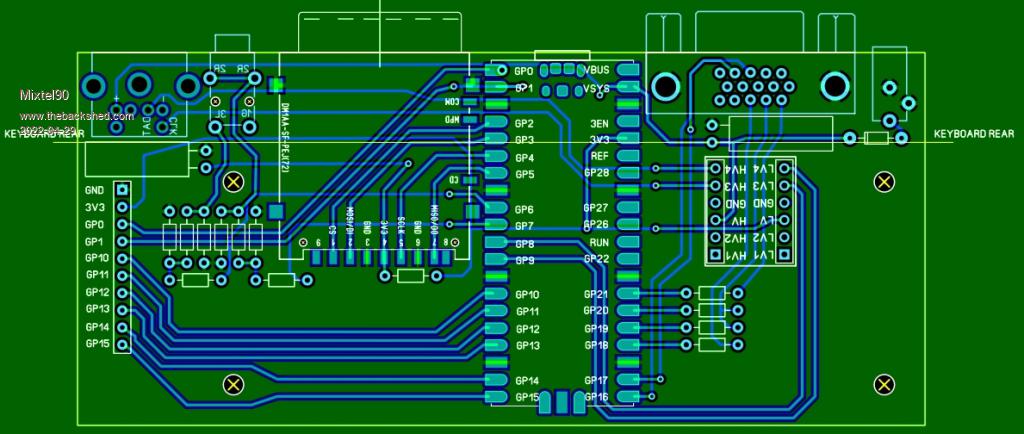 Edited 2022-04-30 03:52 by Mixtel90 Mick Zilog Inside! nascom.info for Nascom & Gemini Preliminary MMBasic docs & my PCB designs |
||||
| Amnesie Guru Joined: 30/06/2020 Location: GermanyPosts: 757 |
As well as with my version; I think you can not get this into a keyboard. Even with an all SMD version only a few keyboards will fit this. BUT: A small footprint version of the pico is always cool, because the orginal PCB is waaaaay to "nested" with all those double and tripple Pico footprints (YES I KNOW, TO SUPPORT Pico accessory-boards etc.) but the problem is, that you introduce a lot of parasitic capacitance. And I highly doubt that it is usefull to even "break out" the VGA lines to the 40pin connector. So I love to see a pcb with the design choice of the Pico facing the micro USB to the back :) I mean this is so cool, that now people can choose the PCB-design which fits their needs! Great job! -Daniel |
||||
| Mixtel90 Guru Joined: 05/10/2019 Location: United KingdomPosts: 8911 |
The point of this design is that it's not intended to go into a keyboard, it goes under it. :) You could screw it to the bottom (using something like #4 x 6mm self tappers with nylon spacer washers) or even use sticky pads to hold it. When you get fed up of it you can just take it off again. I've not managed to get a RTC on it though. It can be done, by making the board longer, but then it wouldn't fit some keyboards - including the one that I'm using to type this. I could mount a SMD chip directly but that's cheating. :) Butchering one of the tiny modules is a possibility. Mick Zilog Inside! nascom.info for Nascom & Gemini Preliminary MMBasic docs & my PCB designs |
||||
| cdeagle Senior Member Joined: 22/06/2014 Location: United StatesPosts: 269 |
Here are two pictures of the Vilros keyboard with a Raspberry PI 4 and a fan/switch on the top. Bought it for $20 on sale. Lots of room. Switch for turning the KB on and off. 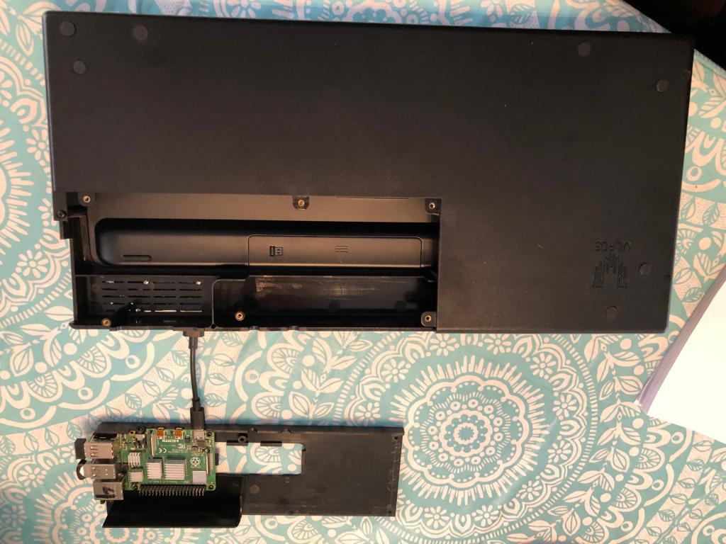 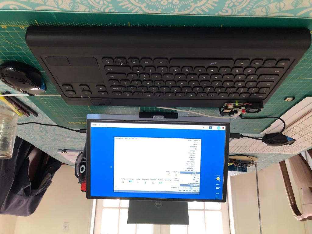 |
||||
| Mixtel90 Guru Joined: 05/10/2019 Location: United KingdomPosts: 8911 |
My problem, when I was looking at a design, is that you have no idea what the keyboard is going to be like. You were lucky finding one with so much space in it. :) Daniel has made a lovely little board system that may well tuck away inside some keyboards. It certainly wouldn't in my PS/2 keyboard. So, my approach doesn't even involve opening the keyboard up (unless you are checking for a safe place to drill holes). It's not as pretty as a truly integrated system, but I think it's probably a good compromise - especially if some way of making a "lid" to cover the 13mm projection could be sorted out. It also gave me some entertainment creating the footprint for surface mounting a PicoMite. :) Mick Zilog Inside! nascom.info for Nascom & Gemini Preliminary MMBasic docs & my PCB designs |
||||
| Volhout Guru Joined: 05/03/2018 Location: NetherlandsPosts: 5931 |
Hi Mick, like your idea. May I make a suggestion. Put the pico at the same side the vga and ps2 are as smd, and put the sd card right under the pico, bottom side. Use the freed up space( wher the sd card was)for a 2x8 angled io header. Then you have all connections at one side. Ther is no linear regulator, that is no problem, but I noticed you have no diodes at the vga. These diodes just conduct at 0.8 v and filter ripple. Leaving them out may show noise in the video depending the monitor( the monitor may clip an thus remove ripple from rgb) Edited 2022-04-30 20:23 by Volhout PicomiteVGA PETSCII ROBOTS |
||||
| Mixtel90 Guru Joined: 05/10/2019 Location: United KingdomPosts: 8911 |
I'd considered something like that. With a microSD it would work well, but a full size SD - the only sort solderable by most people - there is a bit of thickness to consider. I'd thought of putting the SDcard on the same side as the PS/2 and VGA with the Pico underneath it. You may need access to the button. The SDcard is 3mm thick, so if you allow about 2mm for the soldered joints you only lose about 1mm in thickness. I don't think you can plug the Pico's USB in and have a SD card plugged in at the same time though. There's only 1.5-1.6mm between them. That may not be a problem as I envisage that connection only being used for firmware updates. Mick Zilog Inside! nascom.info for Nascom & Gemini Preliminary MMBasic docs & my PCB designs |
||||
| Volhout Guru Joined: 05/03/2018 Location: NetherlandsPosts: 5931 |
Actually, I would consider the uUSB as the power inlet. I have plenty of phone chargers an uUSB cables, but none with barrel connector... PicomiteVGA PETSCII ROBOTS |
||||
| Mixtel90 Guru Joined: 05/10/2019 Location: United KingdomPosts: 8911 |
My problem with that is their long term reliability. Get a problem on there, with a soldered in Pico, and it's not easy - possibly a scrapper. The barrel jack, on the other hand, is cheap and easy to replace. It's also primarily designed to be a power supply connector. Mick Zilog Inside! nascom.info for Nascom & Gemini Preliminary MMBasic docs & my PCB designs |
||||
| Mixtel90 Guru Joined: 05/10/2019 Location: United KingdomPosts: 8911 |
Had a go at making it more compact. Short of getting a steam iron on it I doubt if it will go much further. :) As a surface mounted Pico will be at least 1.5mm thick there's not a lot to gain by changing to SMD resistors and they are more fiddly. The bottom (components / against the table) side: 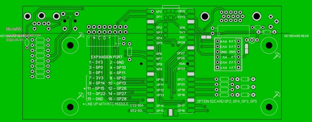 The side that goes against the bottom of the keyboard: 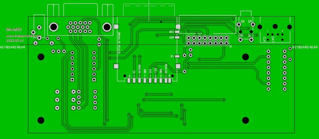 The expansion port (a 2x8 rear-facing box header) will take one of the little RTC modules plugged into pins 7,9,11,13 & 15 (top row, pointing upwards). Unfortunately it covers GP22, but that's hard luck. Unplugging it gives you that back, together with GP14 and GP15. I used a box header so that a 16-way ribbon could be used. The default is to use a MCP linear regulator, but this can be left off and solder blob links changed to enable the SMPS. Audio output is line level only. Unfortunately it's too big for JLCPCB's special $2 offer. :( Mick Zilog Inside! nascom.info for Nascom & Gemini Preliminary MMBasic docs & my PCB designs |
||||
| Volhout Guru Joined: 05/03/2018 Location: NetherlandsPosts: 5931 |
Mick, Nice, sign me up for one! Check if there is solder resist on all pico pads that are not ground. PicomiteVGA PETSCII ROBOTS |
||||
| Mixtel90 Guru Joined: 05/10/2019 Location: United KingdomPosts: 8911 |
I might change the audio filter for your 2-stage "green" curve. It doesn't need much messing about to do. You were right about the solder resist. That would have made it fun to build. lol I've moved the pin names outside the pads too. Mick Zilog Inside! nascom.info for Nascom & Gemini Preliminary MMBasic docs & my PCB designs |
||||
| Volhout Guru Joined: 05/03/2018 Location: NetherlandsPosts: 5931 |
Hi Mick, The 2 stage filter will give better rejection in the 500kHz and higher, so in combination with running the pico powersupply in pwm mmode may work. But the vga will cause 60hz ripple, and we may need somerhing to counter that. Series capacitor with tuned value may work. Then put the series cap from pico pin to filter. Not after the filter since its funtion depends on headset impedance. PicomiteVGA PETSCII ROBOTS |
||||
| The Back Shed's forum code is written, and hosted, in Australia. | © JAQ Software 2026 |
