
|
|
Forum Index : Microcontroller and PC projects : PicoMite PLC project
| Author | Message | ||||
| Mixtel90 Guru Joined: 05/10/2019 Location: United KingdomPosts: 8913 |
I was having a look at RS and Farnell, but the ones I want - say, 1.5A or 2A P-channel - are only available if I want 100 or more now. That's not gonna happen. I can have surface mount, but I don't want to use them because if you blow one it's a pig to change it. There's no rush. I'm unlikely to be rushing out to get a huge quantity of PCBs at the moment (there are the bases at 210mm x 100mm so quite expensive and currently 9 types of IO boards, including the master controller). It only affects the high side output card. At the moment it uses cheap 800mA transistors, which is probably fine for a lot of uses. Mick Zilog Inside! nascom.info for Nascom & Gemini Preliminary MMBasic docs & my PCB designs |
||||
| Mixtel90 Guru Joined: 05/10/2019 Location: United KingdomPosts: 8913 |
@Tinine: I now have a board with 10X non-isolated 24V active low inputs on it. Would that be ok for encoder inputs? @Volhout: 8 of the inputs are on consecutive pins, so I think that makes them easier to read into a PIO. The remaining 2 are still consecutive, but on two of the analogue pins. Whether even a PIO could read 5 encoders at once is something else. :) аWhether the serial interface to the board and processing on the master would be fast enough is something else. ============ I now have a PicoMite sending SPI - that bit was very easy. Getting another to receive it and respond correctly is likely to be more difficult. I considered using master mode from both ends, but the master then has to either keep scanning all nine CS inputs or has to have 9 interrupts open and disable eight when it responds to one. I think it may get hairy. The other way is to synthesise a slave mode as I mentioned previously. At least having CS under user control helps. It's essential to read the clock edges. A rising edge triggers the shift in of one bit and preparing the next bit for tx and the falling edge shifts out the tx bit (using Mode 3). If I've understood it correctly. So glad I took the plunge for the logic analyser. :) EDIT: On looking at the RP2040 Datasheet, there's a way to do duplex SPI on a PIO with some C. However (a) it makes my brain hurt badly and (b) I still don't see how it works as a SPI slave. I'll have to have another look. Edited 2022-06-06 17:24 by Mixtel90 Mick Zilog Inside! nascom.info for Nascom & Gemini Preliminary MMBasic docs & my PCB designs |
||||
| Volhout Guru Joined: 05/03/2018 Location: NetherlandsPosts: 5953 |
Hi Mick, It is not the PIO I worry about. Each sequencer works independently. On the VGA you can decode 4 encoders. On the pico you can do 8 without having to worry about speed. But the single ARM must handle the data stream. Which it perfectly can in assembly, but in MMBasic I would focus on the minumum. As said before, your "PLC" tact (tick) will go down. I would definitely base the control algorithm on a fixed beat (using the SETTICK interrupt) and do all processing in the interrupt routine. Main level would only have a DO:LOOP with some communications. All commands in the main loop must be short (quick) as to ensure maximum stability of the SETTICK defined frequency. If you base communication on UART, you can benefit of it's buffers. Volhout Edited 2022-06-06 17:22 by Volhout PicomiteVGA PETSCII ROBOTS |
||||
| Mixtel90 Guru Joined: 05/10/2019 Location: United KingdomPosts: 8913 |
My hunch (and it's only a hunch) is that UART would be too slow, even if it's buffered. SPI was designed for high speed data on a PCB (as was I2C, which is another possibility but much slower). If I can get it right the data throughput is very high. Buffering isn't needed as it runs on an interrupt system using CS and there is only a single high speed duplex data link at any one time. Yes, the master has to scan all the slaves to get a status flag byte or two, but apart from that there are no long communications as far as I can see and all status bytes are unbuffered and up to date. Nope, I should start calling it a MPC now 'cos that's what I've written on it. :) It's also more in line with how it works. The master can still run on a settick, but the slaves are intelligent sub-commands coupled to IO. Sometimes they are very simple (e.g. output 10 bits) but there's no reason why they should be. What would make sense to me would be to put the decoder reading and he motor control on the same PicoMite so it can run as a closed loop. Possibly two motors and two encoders (if I can find enough terminals) so it can be an X-Y. The master then says "do this" and leaves it to it, apart from perhaps getting a message to say that it's done it. ================ I hope people aren't taking this to be a firm construction project. It *might possibly* be *eventually*, but for the moment it's very much a mind game with trimmings. Even the PCB designs are just me playing to see what's within the scope of such a project. It's not really a "design", although I'm trying to be realistic. The maths shows how unrealistic some of this is: PCBs - minimum order is 5 of any one type. Only a single design can be on one PCB as you are actually charged for each design, not each PCB. Base - 5x 210x100 PCBs IO boards fit 2 on each 100x100, so you get 10 IO boards per order. There are now 9 IO board designs, so that's 90 IO boards in total. For playing I'd probably use 1 full base (to test for signal integrity on the SPI over that length) and a 6-slot (possibly a 3-slot too) so that's not too bad. But there's no way on earth I'd use all those IO boards. The house isn't big enough - apart from the cost of getting all those made and shipped. Also, to fit 2x IO boards on a single 100x100 you'll need to band saw them (or use the score & vice method) as the manufacturer can't v-groove them unless there is a border for the machine to grip. I haven't got space for a band saw. :( The components themselves aren't too bad - I wouldn't attempt to equip the boards that I didn't need. Mick Zilog Inside! nascom.info for Nascom & Gemini Preliminary MMBasic docs & my PCB designs |
||||
| Volhout Guru Joined: 05/03/2018 Location: NetherlandsPosts: 5953 |
Mick, I was thinking along the lines of your distributed control having multiple picos. The quadrature decoder pico would also control the attached motor. So this board would have encoder inputs and motor outputs , PWM of full bridge outputs. Ask Tinine what he favours. At power on, the main pico would initialize the control board with parameters. And during operation it would send commands to move to new position with x speed. This could be UART. There must be an interrupt line where the control board sends it needs support. Either it is ready, or, there is something wrong. No real time interaction between control pico and main pico. That is simply too slow. Edited 2022-06-06 20:05 by Volhout PicomiteVGA PETSCII ROBOTS |
||||
| Tinine Guru Joined: 30/03/2016 Location: United KingdomPosts: 1646 |
Incremental Encoder: The most common supply voltage/signal-level is 5V We need to handle 3 signals; Channel-A, Channel-B and the Index which may be labelled Channel-I or Channel-Z. CHA and CHB are continuous streams of pulses that are 90 degrees out of phase so that direction may be determined. The Index pulse occurs once per revolution and is typically used for homing of the axis. However, it's rare to find a 3-wire industrial encoder anymore because most are now equipped with RS422 line drivers and so we have 6 signal wires, along with 5V and 0V. The controller needs a RS422 line receiver and then the 3 signals are fed to the MCU. Motor Control: The good news is that this can be extremely simple. Simpler in fact than driving a hobby motor with a H-Bridge. A machine fitted with a servo-motor (BLM or BLDC) will already have a driver (amplifier) and the vast majority are configured in "velocity mode". In this mode, our motor command is simply a velocity reference signal. The velocity damping (the Derivative term in PID) is handled by the drive and so our PID filter can be nothing more than the P (Proportional) term. Possibly the I (Integral) term. The driver has velocity scaling so that the maximum required velocity can be set to the maximum command from the controller. We provide the proportional gain coefficient, Kp: Do Pause Sample_Time Error = Commanded_Position - Encoder_Reading PWM_output = Kp * Error Loop The above is intended as pseudo-code because it doesn't account for the code execution time. This could be handled in SETTICK. The Sample_Time to be 10ms or less. Obviously, this only keeps the axis in-position. To move the motor to the desired position at the desired Velocity (encoder_counts/sec), including Acceleration/Deceleration (encoder_counts/sec/sec), We need to include a trajectory generator which could be handled in either the ISR or the main. As this is all based on sample_time, it's not necessary to have multiple motors on one MCU. It's just as easy to interpolate across multiple MCUs а  а аCraig Edited 2022-06-06 22:02 by Tinine |
||||
| Volhout Guru Joined: 05/03/2018 Location: NetherlandsPosts: 5953 |
Hi Tinine, Your pseudo code is not far off from the actual code if you only do P. And using PAUSE with 10ms is absolutely doable. You need to read from the PIO which takes 0.1ms. Do the math, which takes 0.1ms, then write to PWM, which takes 0.1ms. So your loop would roughly be 10.3ms. Not much off from a SETTICK 10. the PWM would be 0-20mA? Or +/-10V I guess?. Is there any info on what speed is needed not to overshoot the index signal? 10% or so? The index pulse could be handled in main. The trajectory control is only needed when your Kp needs to be adjusted (non linear or load dependent). But normally that value would be tuned for stability (no jitter). Edited 2022-06-07 00:07 by Volhout PicomiteVGA PETSCII ROBOTS |
||||
| Tinine Guru Joined: 30/03/2016 Location: United KingdomPosts: 1646 |
Index overshoot is no problem but the important thing is to capture the encoder reading as precisely as possible on seeing the index. Then we know where we are as an offset of physical zero. Very rarely do I ever change Kp after initial tuning. I have had hydraulic axes where you absolutely don't want to use the integrator (Ki) unless you like having your machine dancing across the floor. So I can apply increased Kp until within tolerance...it's more subtle  The trajectory control is required to move from point-A to point-B at the specified Acceleration/Slew/Deceleration. With just the above loop, the axis would jump at full velocity and zero ramp because its purpose is to instantly be at the commanded position. The Trajectory Generator "discretizes" (is that a word?) the move distance in to X encoder_counts per sample period. So, forgetting accel/decel, If we wanted to move the axis 1000mm in exactly 1 second, the trajectory generator, also running at 10ms, would increment the Commanded_Position by 10mm for each iteration and the PID loop (only P) would drive the motor. So 10ms = 100Hz and 100 * 10mm = 1000mm. Motor Command: +/- 10V (kinda sounds old fashioned but it's still the universal standard)  |
||||
| Volhout Guru Joined: 05/03/2018 Location: NetherlandsPosts: 5953 |
The deceleration would happen automaticaaly since the PWM is proportional to the error, and the error get smaller at the approach of the set point. But yes, we would need acceleration curve if the Velocity controlled amplifier has no limits for acceleration. But that is exactly what the I in PID does. It integrates.... So you could have an Ki that is positive, in which case you could use a smaller Kp, or you could have an Ki that is negative. Normally, when you tune Ki, Kp and Kd you could achieve acceleration, deceleration, and still get a good stop at the end point without overshoot. The only time I needed acceleration and deceleration curves was when controlling a stepper motor (on feedback loop) to overcome the innertion in the motor and wheels. That was forward control, no feedback loop. Actually, after I played with an MMBasic written PID I realized how simple it actually is. In University they tought us the math, and at that time I could not fully understand it. I passed the exam, but never really was able to use it in real life. Until I started playing with the basic simple math in Basic and graphed it out.Toy with Parameters, and get ti right. Of coarse you cannot toy with parameters when steering an huge container ship through the SUEZ canal, but they probably didn't either...... The acceleration curves for the Micromouse stepper motors where "tuned" by the mouse itself. On a small section of the maze, I let it run back and forth (first in s=a straight line) and vary parameters until it had the fastest movement, and did not miss any markers. Was actually a very simple program that tuned the parameters. I never made it to tune parameters for the corners.. (straight line is easier, in a corner and overshoot measn a crash). Edited 2022-06-07 01:46 by Volhout PicomiteVGA PETSCII ROBOTS |
||||
| Mixtel90 Guru Joined: 05/10/2019 Location: United KingdomPosts: 8913 |
So, from a hardware angle, you'd want a board with a RS422 receiver for the feedback and a +/-10V to control the motor? Would it need to send RS422? Mick Zilog Inside! nascom.info for Nascom & Gemini Preliminary MMBasic docs & my PCB designs |
||||
| Tinine Guru Joined: 30/03/2016 Location: United KingdomPosts: 1646 |
I prefer to follow the profile exactly as commanded. For example; I might want to decelerate from 3,000RPM to 0RPM in exactly 12.5 seconds. Not a problem...keep the Kp high enough and it will follow the profile, perfectly Craig an00115-001-Trapezoidal-Move-Calculations-ABB.pdf |
||||
| Tinine Guru Joined: 30/03/2016 Location: United KingdomPosts: 1646 |
No. There is no comm's protocol. It's just like counting pulses on any other pin. Remember our discussion about checksum vs CRC? Well this is what I was referring to when I stated that CNC machines rely 100% on pulse integrity. Lose a few pulses here and there and your machine could self destruct Craig |
||||
| Tinine Guru Joined: 30/03/2016 Location: United KingdomPosts: 1646 |
@Volhout I forgot to mention that the drives, in velocity mode, have their own integrator. 0RPM means 0RPM. An external force tries to displace the rotor and they will pump all available current in there to resist. It feels like a locked rotor...pretty cool Craig |
||||
| Mixtel90 Guru Joined: 05/10/2019 Location: United KingdomPosts: 8913 |
So 5V, GND, 3x 5V open collector inputs (pullups on the board) and the +/-10V? Mick Zilog Inside! nascom.info for Nascom & Gemini Preliminary MMBasic docs & my PCB designs |
||||
| Tinine Guru Joined: 30/03/2016 Location: United KingdomPosts: 1646 |
Drat....I was waiting for this I kinda went quiet on this because I felt bad, after all the contributions...I went with my original crude-ish LM358 filter....I know that it works  BUT now we have an excuse to refine the design, right? Craig |
||||
| Tinine Guru Joined: 30/03/2016 Location: United KingdomPosts: 1646 |
I'm still using the 3486 line receiver due to availabilty. CD4050 for level shifting. 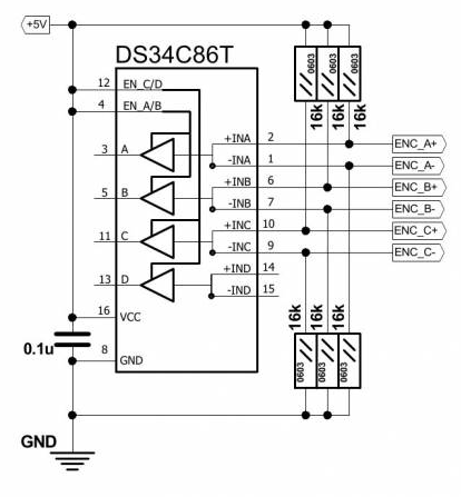 Craig |
||||
| Mixtel90 Guru Joined: 05/10/2019 Location: United KingdomPosts: 8913 |
3V3 | ___ 10k ___ | |', +-----|+ ; | | :-------------+---- +/-10V 5kHz pwm -----[ 4k7 ]----------+|- ; | 3V3 | ||,' | ___ | | 8k2 +---[18k]---[12k]--+ ___ | | | '-------|220nF|----' GND LM358 on +/-15V supplies mmmmmmmmm. Glad to be of service! Mick Zilog Inside! nascom.info for Nascom & Gemini Preliminary MMBasic docs & my PCB designs |
||||
| Tinine Guru Joined: 30/03/2016 Location: United KingdomPosts: 1646 |
@Volhout: I don't know how many papers I have read re: auto-tuning...can get pretty hairy  The one thing that they all seem to have in common? [paraphrasing the last paragraph] "When all is said and done, the engineer usually ends-up manually tuning" I work with these digital drives all the time and I have to say that it's the one area where digital didn't make life easier. I basically switch-off all of their features, select "torque mode", which essentially makes the drive a dumb transconductance device and handle the full PID in my own controller. Otherwise, if the client needs to replace a unit, he'd have to hook-up a laptop and go through confusing menu after confusing menu. Even connecting to the manufacturer via TeamViewer.  Craig |
||||
| Mixtel90 Guru Joined: 05/10/2019 Location: United KingdomPosts: 8913 |
I'm not sure how much of a goer this could be, given the limitations on pcb area. Adding chips takes up space - and I don't want to use SMD unless it's the only possible way - and even then I'd rather not do it at all. So far it needs: A dc/dc converter to get +/-15V, preferably from the 24V supply. A LM358 with associated components A DS3486T with associated components A CD4050 That's crowded for this design. Mick Zilog Inside! nascom.info for Nascom & Gemini Preliminary MMBasic docs & my PCB designs |
||||
| Tinine Guru Joined: 30/03/2016 Location: United KingdomPosts: 1646 |
Hey, that's my crude filter with different resistor values I actually went with a gain that results in +/- 9.9V to utilise the full DAC resolution. Craig |
||||
| The Back Shed's forum code is written, and hosted, in Australia. | © JAQ Software 2026 |
