
|
|
Forum Index : Microcontroller and PC projects : Will the Pico directly drive this MOSFET?
| Author | Message | ||||
| Mixtel90 Guru Joined: 05/10/2019 Location: United KingdomPosts: 8682 |
Somewhere between 100R and about 470R is common for the gate resistor. You can work it out, knowing the available current from the pin and the gate capacitance of the mosfet, but it's hardly worth it in most cases. Increasing the resistor too far results in the mosfet switching slowly, dissipating power as it does so, with consequent rise in temperature. Too ow a value doesn't restrict the surge enough, sometimes causing a micro pin to go into overcurrent. With a scope you can see what's happening, but use a high impedance probe or the scope will load the gate voltage and it'll be misleading. I'd go for a starting value of about 270R for the PicoMite and see if switching is ok, with not too much heating. (It'll only dissipate much during switching, so a steady load is fine, PWM will warm things up.) Mick Zilog Inside! nascom.info for Nascom & Gemini Preliminary MMBasic docs & my PCB designs |
||||
| lizby Guru Joined: 17/05/2016 Location: United StatesPosts: 3699 |
In order to test various TO-220 N-CH logic level mosfets with the picomite, I cut the nearly useless IRF540 (up to 9V for full on--why don't they use IRL520 or IRL540 or other logic level mosfet?) off of one of these mosfet modules and soldered on a 3-pin female header:  The load was a nominal 50W 12V LED. This is my test program--full on for a second, off for a second, on for a second, off, then ramp at 1000Hz from 0 to 100% duty cycle and back down twice, then full on for a minute: dim integer i,j setpin 1,dout pin(1)=1 pause 1000 pin(1)=0 pause 1000 pin(1)=1 pause 1000 pin(1)=0 pause 1000 setpin 1,pwm0A for j=1 to 2 for i=0 to 100: pwm 0,1000,i: pause 20: next i: pause 2000 for i=0 to 100: pwm 0,1000,100-i: pause 20: next i: pause 2000 next j pwm 0,1000,100 pause 60000 pwm 0,1000,0 I tested FQU13N06TU, IRLB8743PBF, IRL540NPBF, IRLZ44N. All worked with 3V3 from the picomite with no problem. (Note: I got an error message with PWM 0,OFF, which the manual says should work and should release the pin.) PicoMite, Armmite F4, SensorKits, MMBasic Hardware, Games, etc. on FOTS |
||||
| pwillard Guru Joined: 07/06/2022 Location: United StatesPosts: 339 |
The IRF540 is barely capable of running a big load current with only 5V at the gate without becoming a room heater. �I guess it depends on your specific use case as to whether or not the IRF540 is *workable* with logic-level circuits. (It's probably awful with 3.3V I just never bothered to see for myself.) � The fact is though... the IRF540 is as plentiful as the 2N3906/2N3906 BJTs. �Tons are available and are dirt cheap... so they get bought to keep the board price down. Swapping them out for a better match with 3.3V logic is a good plan in my opinion. You can get 2N3906 for $0.02 today... back in 1978, it would be more like $0.70 each from DIGIKEY (taking inflation into account). With 3.3V GPIO... the part better say "LOGIC" in the datasheet or have IRL in the name before I'm even gonna waste solder on it. One annoying factor with MOSFETS in my experience... is once you find a good part to keep on hand... manufacturers will make it obsolete on you. Edited 2022-06-10 12:06 by pwillard |
||||
| Volhout Guru Joined: 05/03/2018 Location: NetherlandsPosts: 5806 |
Dear Developers, If you want a MOSFET (or in that matter, IGBT) to drive serious loads (I am not talking about a few mA) then you MUST add a driver circuit for the gate. Even with logic level FET's, you cannot drive them directly from a microcontroller. Reason: The microcontroller has relatively high output impedance, and has virtually NO protection against voltage spikes (especially not the picomite). Every MOSFET has a capacitance between drain and gate. And when the drain switches a load ON and OFF, part of that switching energy will reflect back to the gate. That is why you need a robust driver circuit so: a/ the FET stays ON (the energy reflected back to the gate can also switch OFF the FET again). b/ the microcontroller is isolated from that energy. Why do we have "logic level FET's" ? In some applications there simply is no higher voltage than 5V, unless it is specifically created by a boost convertor. In that case a logic level FET can help. But also logic level POWER MOSFET's need a driver circuit. The only application where you could drive a MOSFET directly from a microcontroller is when you switch it SLOWLY. And these applications are rare, and mostly low power (the MOSFET will heat up significantly during the OFF/ON/OFF transitions). Circuits that drive the gate with a series resistor of 1k, and add a gate-source capacitance of 100nf....or similar. If you include a driver circuit, the level becomes less of an issue, unless you simply have no higher voltage available. Then a logic level FET may come in handy. EDIT: lizby's test uses 12V (relatively low voltage) and a resistive load (glow bulb/LED). That is the least stressing of all tests you can perform. Try switching a car ignition coil, and see if you picomite survives.... Edited 2022-06-10 18:55 by Volhout PicomiteVGA PETSCII ROBOTS |
||||
| pwillard Guru Joined: 07/06/2022 Location: United StatesPosts: 339 |
I believe that Volhout is talking about IC's like the Microchip TC1427 or TC1428 which can take 3.3V/5V logic and drive a Mosfet with it. Mouser sells these for about $1.50 and you can still get them in Though-Hole DIP for experimentation. |
||||
2001cpx Regular Member Joined: 03/10/2013 Location: CanadaPosts: 59 |
I always use optocouplers with mosfets, I've never had a problem. like this taken from google 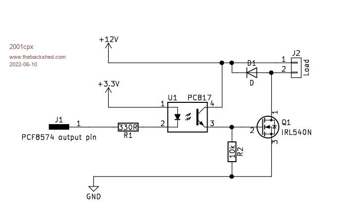 "Color Maximite,(Duinomite-Mega,Mini),CGmmStick,GCmicroboard2b,Micromite + explore 64,100,LCD backpack,Lcd Backpack V2,TFT Backpack,Micromite Extreme,Armmite L,F,H,CMM2" |
||||
| Tinine Guru Joined: 30/03/2016 Location: United KingdomPosts: 1646 |
 That just feels better after experiencing the USB disturbance. That just feels better after experiencing the USB disturbance.Would I simply add a voltage dividing resistor for 24V? 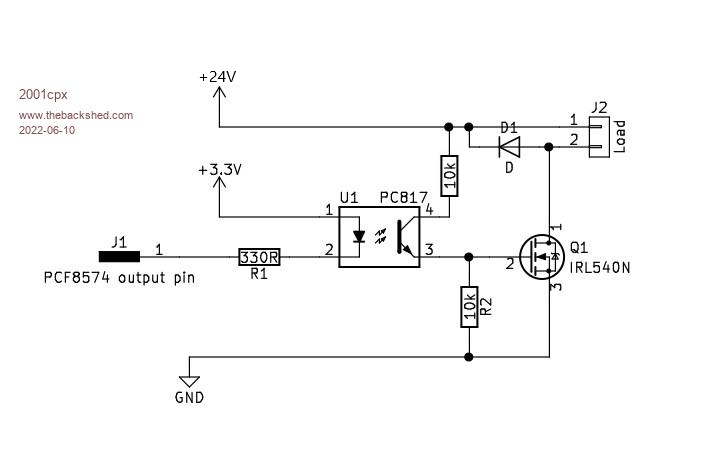 Craig |
||||
| Mixtel90 Guru Joined: 05/10/2019 Location: United KingdomPosts: 8682 |
That should be ok. The IRL540N, for example, has a maximum gate-source voltage of 16V so you have to stay within that. You can probably drive the LED in the opto at two or three mA. Mick Zilog Inside! nascom.info for Nascom & Gemini Preliminary MMBasic docs & my PCB designs |
||||
| CaptainBoing Guru Joined: 07/09/2016 Location: United KingdomPosts: 2171 |
and you can miss out D1 if the load is resistive |
||||
| Volhout Guru Joined: 05/03/2018 Location: NetherlandsPosts: 5806 |
I design electronics for a profession, and typical my customers are very keen on reliable designs that survive all kinds of abuse, and meet robustness requirements set forth in worldwide standards. Sometimes I forget this is a website that is manned with enthousiastic guys that want to do maker projects with tools they posses, and simply want to makes things work. I want to appologize for my previous message that may have discouraged people to "just toy with the parts, and have fun". They have a name for that : professional misformed minds... Please excuse me for being so. Volhout PicomiteVGA PETSCII ROBOTS |
||||
| Mixtel90 Guru Joined: 05/10/2019 Location: United KingdomPosts: 8682 |
Your expertise is invaluable, Volhout - to me anyway. :) My field used to be electrical control gear usually from 24V to 11kV (and in one case a 36kV indoor 3-phase switch fuse!). Anything lower was usually a bit of PLC stuff. My electronics is strictly hobbyist, and I probably know more about valves than MOSFETs. :) With that background I'm happy to see any contributions from those with a lot more experience. Mick Zilog Inside! nascom.info for Nascom & Gemini Preliminary MMBasic docs & my PCB designs |
||||
| CaptainBoing Guru Joined: 07/09/2016 Location: United KingdomPosts: 2171 |
what you talking about Harm? you are fine. I re-read your post and I really can't see anything even remotely "off". You know your stuff and you share without hesitation or expectation. I for one among many value your input - highly.  |
||||
| Tinine Guru Joined: 30/03/2016 Location: United KingdomPosts: 1646 |
Heck guys, please keep the opinions flowing...I am absolutely loving this. Doesn't do anyone any good to agree out of politeness. I realise that I am the worst for being abrupt and stubbornly opinionated but I have little respect for anyone who is afraid to force their point of view. Like I stated...loving this and you guys are helping me to become more of an engineer than a hack � Craig Edited 2022-06-11 06:59 by Tinine |
||||
| lizby Guru Joined: 17/05/2016 Location: United StatesPosts: 3699 |
I am very grateful for the input of people here who are actually making their livings working with electronics hardware, like Volhout, Tinine, the Cap'n or who have, like Mick. We amateurs can learn something. I was familiar with the blowing up of MOSFETs improperly driven or overdriven from the reports of those in another room of the shed burning up the MOSFETs in their home-built inverters, but I was unaware of the issue of the MOSFET passing through (or is it generating?) a spike which might harm the microprocessor. So please, keep these tips coming. I'm not sure I've ever turned on anything but an LED with a MOSFET, and 12V, 4+A is probably the maximum. If I ever turn on a motor, I'll know to protect the micro with a proper driver or opto. By the way, in Paul_L's application where a MOSFET would be switching 12V to turn on a relay switching 120V, should I worry about that spike? PicoMite, Armmite F4, SensorKits, MMBasic Hardware, Games, etc. on FOTS |
||||
| Tinine Guru Joined: 30/03/2016 Location: United KingdomPosts: 1646 |
Pretty much validates ALL opinions Craig |
||||
| pwillard Guru Joined: 07/06/2022 Location: United StatesPosts: 339 |
True Tinine. Nick G's web pages have saved me from making a lot of mistakes. |
||||
| lizby Guru Joined: 17/05/2016 Location: United StatesPosts: 3699 |
Not the "driver needed" one, especially since the examples given are for switching motors. That may have been more detail than the author wanted to go into--if he even was aware if the issue. PicoMite, Armmite F4, SensorKits, MMBasic Hardware, Games, etc. on FOTS |
||||
| Paul_L Guru Joined: 03/03/2016 Location: United StatesPosts: 769 |
Lance, if we use the small Chinese opto-coupled relays to provide the coil current for the bigger relays off the board I don't think there will be any problem, except for the unknown quality of the Chinese relays. These relay boards should therefore be easily replaceable in my dark and dusty cellar. Paul in NY |
||||
| Mixtel90 Guru Joined: 05/10/2019 Location: United KingdomPosts: 8682 |
The Chinese relays probably aren't too bad - watch their voltage rating though. As you are only switching relay coils there won't be a lot of current problems, especially at 28V AC (not 28V DC - that can give contact welding problems with cheap relays at any current). I've had little Chinese relays in the past and have been pleasantly surprised to find that pretty good data sheets were available for them. Whether they told the truth is something else, of course. :) Mick Zilog Inside! nascom.info for Nascom & Gemini Preliminary MMBasic docs & my PCB designs |
||||
| phil99 Guru Joined: 11/02/2018 Location: AustraliaPosts: 3086 |
"The Chinese relays probably aren't too bad " That has been my experience too. A 240V / 10A one that I am using in the thermostat for my heat pump hot water system has been going for five years. The compressor running current is 5.3A. I am not sure what the start current is but it's enough to stall a 4 KVA generator with a 30A surge rating. The large back EMF at switch off doesn't bother it either. |
||||
| The Back Shed's forum code is written, and hosted, in Australia. | © JAQ Software 2026 |
