
|
|
Forum Index : Microcontroller and PC projects : PM: 5" TFT dual-PM based PCB...
| Author | Message | ||||
| Tinine Guru Joined: 30/03/2016 Location: United KingdomPosts: 1646 |
@Volhout If I built a manufacturing facility from scratch, it would be 100% based on MMBasic control systems and Android HMIs. There is no better MTTR (mean-time-to-repair). A standard platform, based on the RP2040 that could be adapted to anything/everything is what I would shoot for. Of course, for real-time control, I would use the Propeller as a slave to an MMBasic RP2040. A control failure on a Friday evening? I might be an hour late for the pub but the darned machine would be up and running.  Craig |
||||
| Tinine Guru Joined: 30/03/2016 Location: United KingdomPosts: 1646 |
Forgot to mention that my current design consists of a master RP2040, Prop-2 slave, Prop-1 slave and four slave RP2040 I/O expanders. Three of the I/O expanders have a single Click socket and there is another Click socket for the Prop-2. Slight overkill happening here Craig |
||||
| Volhout Guru Joined: 05/03/2018 Location: NetherlandsPosts: 5953 |
Hi Craig, that was not the question. Question was wat Click modules you used before (on E100) for your setups. The E100 has 2 sockets, so what exactly where you expanding the system with.? Volhout PicomiteVGA PETSCII ROBOTS |
||||
| Tinine Guru Joined: 30/03/2016 Location: United KingdomPosts: 1646 |
Sorry, I had assumed that you'd read my earlier post  |
||||
| Mixtel90 Guru Joined: 05/10/2019 Location: United KingdomPosts: 8913 |
I'll have another look at Click, I think. I'd like to reserve one SPI for a display/SDcard though. I suppose anything else can go on the Click sockets (if I can wiggle the PCB tracks enough). COM, the remaining SPI and I2C might have to get shared if any more than a couple of Clicks are needed. Does that sound ok? They aren't really of much interest to me other than as a technical challenge. Without MMBasic support there's no point. ;) It may take some time though, I'm in the middle of DIY with a bit of a deadline. Edited 2022-09-14 19:04 by Mixtel90 Mick Zilog Inside! nascom.info for Nascom & Gemini Preliminary MMBasic docs & my PCB designs |
||||
| Tinine Guru Joined: 30/03/2016 Location: United KingdomPosts: 1646 |
E-100: 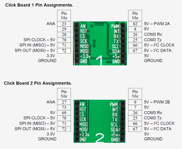 Craig |
||||
| Mixtel90 Guru Joined: 05/10/2019 Location: United KingdomPosts: 8913 |
It may be a lot of level shifting to fit in, for analogue as well as digital. It depends on the modules. I suspect that most will assume 5V systems. Also, level shifting on SPI *might* restrict the speed. Mick Zilog Inside! nascom.info for Nascom & Gemini Preliminary MMBasic docs & my PCB designs |
||||
| Tinine Guru Joined: 30/03/2016 Location: United KingdomPosts: 1646 |
I don't know how common 5v-only modules are. There is usually a jumper selection on the module and the default of the ones that I have used is always 3v3. Craig |
||||
| Mixtel90 Guru Joined: 05/10/2019 Location: United KingdomPosts: 8913 |
Good - I don't want to put level shifters in. It makes life complicated. :) Mick Zilog Inside! nascom.info for Nascom & Gemini Preliminary MMBasic docs & my PCB designs |
||||
| Tinine Guru Joined: 30/03/2016 Location: United KingdomPosts: 1646 |
@Mick I see that some modules are stackable and apparently, this one has a "multiplexer to avoid conflict with other functions driven by the same GPIOs." Not every hobby project will justify these costs but it's nice to have the option of using standard components that can be sourced by the end-user, in the event of a failure.  Craig |
||||
| Volhout Guru Joined: 05/03/2018 Location: NetherlandsPosts: 5953 |
So I guess you can do following: 1/ parallel connect all sockets for I2C and SPI (CLK/MOSI/MISO) 2/ parallel all sockets for 5V, 3.3V and GND 3/ Give the sockets individual CS+RST signals (DOUT), and AN (AIN) 4/ Whenever possible give individual RX and TX Since pico is limited to 3 x AIN, we should be able to support 3 sockets Volhout Edited 2022-09-15 01:05 by Volhout PicomiteVGA PETSCII ROBOTS |
||||
| Tinine Guru Joined: 30/03/2016 Location: United KingdomPosts: 1646 |
Oh, I should've remembered this. They do have level translators. But I guess that they are just covering all bases:  Craig |
||||
| Mixtel90 Guru Joined: 05/10/2019 Location: United KingdomPosts: 8913 |
Tough. You get 3V3 only from me. 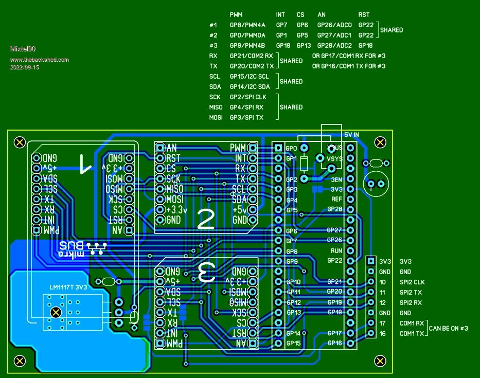 ;) Mick Zilog Inside! nascom.info for Nascom & Gemini Preliminary MMBasic docs & my PCB designs |
||||
| Tinine Guru Joined: 30/03/2016 Location: United KingdomPosts: 1646 |
Awesome  But I need a special version Imagine those headers that stick out on the other side (for the Pico). I could plug my Waveshare display into it, right? But now the Click sockets stick out to one side instead of behind the display. No clue at this point what I/O clashes there would be.  Craig |
||||
| Mixtel90 Guru Joined: 05/10/2019 Location: United KingdomPosts: 8913 |
In theory... by default #3 shares COM2 with #1 and #2. You have SPI2 to use for the display, with GP16 for DC and GP17 for RESET. Tit CS low as there's only the display on the bus. That's for a basic ILI9341. No backlight control, touch or SD card. Alternatively, use COM1 to connect to another PicoMite connected to the display of your choice. �:) �You could also use one or two of the SPI lines as interrupts, I suppose. In your case you could connect COM1 to a cog. You could also communicate with a second PicoMite using SPI, so #3 could use COM1. Unfortunately there's a finite number of pins, which is why #1 and #2 share a RST line. I suppose I could have put GP25 into use... It's not designed as a backpack. The fixing holes are wrong, as is the overall size. You'd be better off running a short SPI or COM lead to a backpack board as there's not enough IO left to be useful.. Edited 2022-09-15 03:46 by Mixtel90 Mick Zilog Inside! nascom.info for Nascom & Gemini Preliminary MMBasic docs & my PCB designs |
||||
| Volhout Guru Joined: 05/03/2018 Location: NetherlandsPosts: 5953 |
Does the ili9341 use 5V for backlight? In the experimenters board the pico was not socketed. When you rotate click sockets 2 and 3 they could overhang the pico when mid or large sizeclick modules are used. Maybe you could save 1 pin by sharing all 3 reset lines, that would not impact funtionality. Edited 2022-09-15 06:22 by Volhout PicomiteVGA PETSCII ROBOTS |
||||
| Volhout Guru Joined: 05/03/2018 Location: NetherlandsPosts: 5953 |
PicomiteVGA PETSCII ROBOTS |
||||
| Mixtel90 Guru Joined: 05/10/2019 Location: United KingdomPosts: 8913 |
The later versions use a transistor to switch the backlight LED. There's an on-board LED resistor. The transistor base has a resistor out to the LED pin so you can just link it to just about any voltage to switch it on or use PWM to dim it. Mick Zilog Inside! nascom.info for Nascom & Gemini Preliminary MMBasic docs & my PCB designs |
||||
| Volhout Guru Joined: 05/03/2018 Location: NetherlandsPosts: 5953 |
But it needs 5V at the display header.... PicomiteVGA PETSCII ROBOTS |
||||
| Mixtel90 Guru Joined: 05/10/2019 Location: United KingdomPosts: 8913 |
Should there be a single reset button that simply resets everything or are the Click modules really intended to be reset individually as needed? The Click "specification" is poor, to say the least. It goes into fine detail about module sizes, types & positions of screen printing etc. but is extremely sparse on anything to do with how the things are supposed to work. There isn't even a pin by pin definition of what they do or even the range of voltages and current limits allowed for a module. Yes, you can make your own module to the "open" specification but the chances of it working with anything else could be remote. EDIT: As I can't find a definitive spec that's what you're getting - a single reset button that does the lot. That way I get two spare I/O which are on the GPIO header. Useful for connecting a display. I've turned #2 and #3 round and also rotated #1 through 180 degrees as it made the traces easier. It'll now take large modules in #2 and #3 positions and medium in #1, all within the footprint of the pcb. 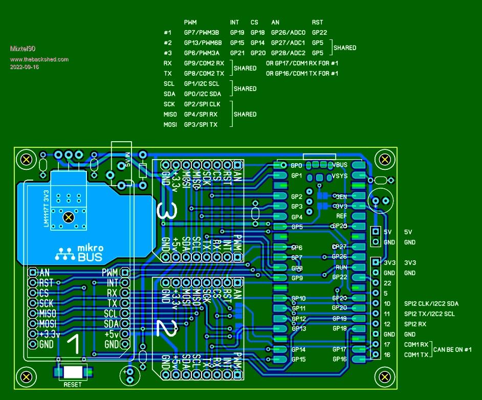 Edited 2022-09-16 01:59 by Mixtel90 Mick Zilog Inside! nascom.info for Nascom & Gemini Preliminary MMBasic docs & my PCB designs |
||||
| The Back Shed's forum code is written, and hosted, in Australia. | © JAQ Software 2026 |
