
|
|
Forum Index : Electronics : Good money after bad - Solar upgrade time
| Author | Message | ||||
| analog8484 Senior Member Joined: 11/11/2021 Location: United StatesPosts: 204 |
Great build. This is something I have wondered about. Given the split-phase we use in North America, it seems a bit risky not monitoring the neutral current. |
||||
| KeepIS Guru Joined: 13/10/2014 Location: AustraliaPosts: 2197 |
I guess it depends on what type of loads the Inverter will be subjected to, that was the problem I stressed over after building each Inverter. What is the Maximum continuous power I want to run, but more importantly, what is the highest SURGE power that I expect the Inverter to handle? NANO:Inverter V 8.2ks - Linux AvrDude GUI script V4.1 |
||||
| oreo Senior Member Joined: 11/12/2020 Location: CanadaPosts: 133 |
Thank you! I am thinking that the temperature sensor on the transformer will protect it in case of current imbalance. The overall current draw limit, protects the electronics. I was hoping to get an idea of what the electronics is capable of, and then setting my current in a similar fashion. I guess I will take it one step at a time. I did remove a turn from each inductor, but didn't notice any real change in my shortish period of testing. One thing I did notice, was that the current draw at idle can change when the noise oscillates up and down in amplitude. At one point, with the noise at maximum, the unit was drawing 21 watts, and after it cycled down to be quiet it was back to 17.5 watts. This is not always the case though as sometimes the noise ramps up and I don't see a significant change in current/power. After doing the testing, I did install the 34uH choke made from the Amorphous cores. I glued the 4 cores together and filled the air gaps using silicon. Unfortunately it was low strength silicone but it was all I had on hand. I have not noticed any noise being generated by the core, but need to do some more testing. Lots of room on these inductors for wire! 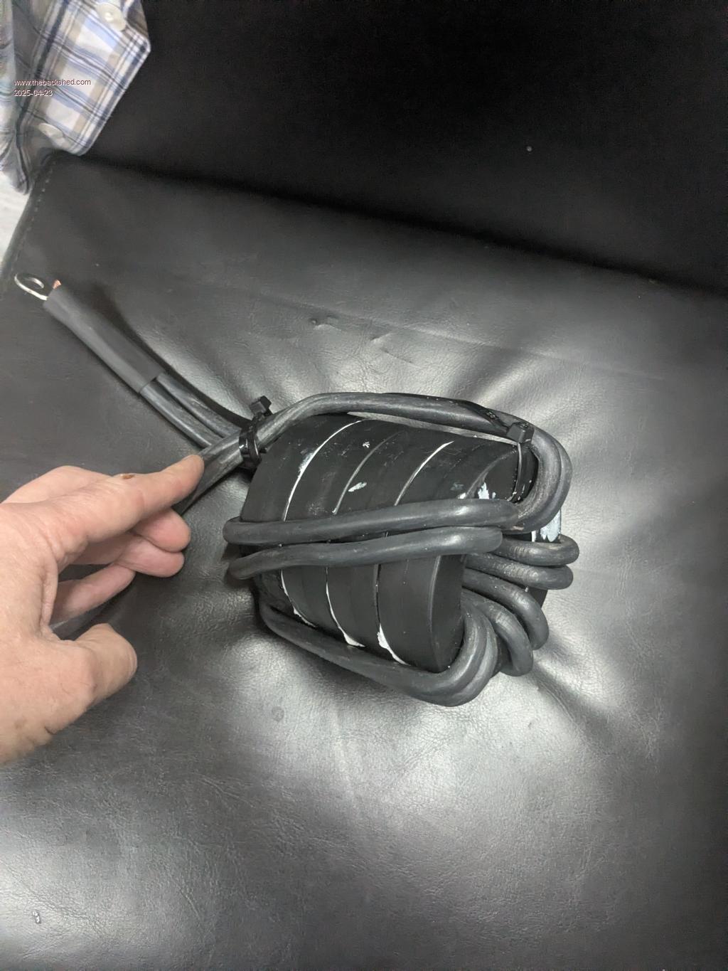 Greg |
||||
| KeepIS Guru Joined: 13/10/2014 Location: AustraliaPosts: 2197 |
I have never glued the cores together, just wrapped a layer of tape around the stacked cores, they have never made a noise, they run cold, only cable heating can warm them, and that is minimal in my inverter. I have posted before about a slight noise, like a 1Hz or slower cycling hum that can only be heard at Idle. The Idle current can be seen rising and falling a small amount as this 1Hz "wave" slowly crawls through the Toroid, usually I need to put my ear right next to the toroid to hear it and I've noticed it on most of my builds. However once the Toriods were in the cabinet it was inaudible, especially since I have a very small AC load on my Inverters that is always on. Wiseguys single board design is capable of running at 8kW for some time, the limit is more possible PCB bus heating and DC and Toroid connection heat, I had no air flow over the power board when I did that test, and the single Inverter could handle 600A Peak DC input of Surge startup current. The unknowns are FETS and the higher Voltages that you use, you will have lower current and possibly less heat in the high current Connections, but Peak power may still be less depending on the FETS at higher voltages. NANO:Inverter V 8.2ks - Linux AvrDude GUI script V4.1 |
||||
| wiseguy Guru Joined: 21/06/2018 Location: AustraliaPosts: 1297 |
I meant to comment on this a few days ago, not sure if you are referring to an iron core or a Ferrite core. If it was Ferrite I would strongly suggest that is not the right way to go. Gapped Ferrite will still saturate with a very sharp knee from my experiments. They also have a lot of audible noise which is difficult to suppress. End result is in an overload event they can detonate FETs with little warning. The sendust/powdered iron type cores are very forgiving and have a really soft saturation behaviour. I started advocating for them in ~ 2019, after some early experiments with various materials and is all I use now. Dex tried using sendust Ecores - my bad suggestion - they did not saturate but were difficult to wind and their noise emission was unacceptable and could not be muted effectively, then he went to ring cores, problem solved. If at first you dont succeed, I suggest you avoid sky diving.... Cheers Mike |
||||
| oreo Senior Member Joined: 11/12/2020 Location: CanadaPosts: 133 |
Thanks for the update and the further build details KeepIS! Wiseguy, the choke I am testing is not ferrite, but amorphous nanocrystalline like this . A gapped choke using this core still saturates pretty hard, maintaining 34uH up to 160amps, and then kneeing down quickly finishing at about 5uH at 350 amps. I am not seeing any audible noise issues with this choke so far, but have only tested up to 4kw inverter power so far. It is unlikely that I would be relying on this core on it's own. Greg |
||||
| analog8484 Senior Member Joined: 11/11/2021 Location: United StatesPosts: 204 |
Assuming you currently only have one choke, I wonder if splitting the choke into 2 (one on each leg and each with 1/2 inductance) would help? I believe that's what KeepIS did. Interesting. What's the main reason you chose amorphous nanocrystalline over Sendust cores? |
||||
| oreo Senior Member Joined: 11/12/2020 Location: CanadaPosts: 133 |
Actually I am using 2 sets of cores, but only replaced 1 of them with amorphous nanocrystalline. Just trying different cores I already have. I purchased the 4 amorphous cores because they were cheap and looked interesting. Cores Initially from this same EBAY vendor, I had ordered 20pcs of MS225 sized sendust cores but they shipped MS184 sized sendust cores. They refunded my $, but said they didn't have any of the correct cores in stock (yet they continue to advertise them for sale, even after I sent them 2 emails asking what was going on). Anyway the thickest wire I can get onto these cores is #6 awg, which is a little on the thin side. I did a bunch of testing, and the reality is they should be ok (72v=less current, and I plan on using 2 transformers, so will be using 2 sets of 2 chokes). I mounted a couple of extra fans beside them to keep them cool(ish). One core was wound with 6awg wire covered with heatshrink, while the other uses magnet wire with the equivalent of 6awg. 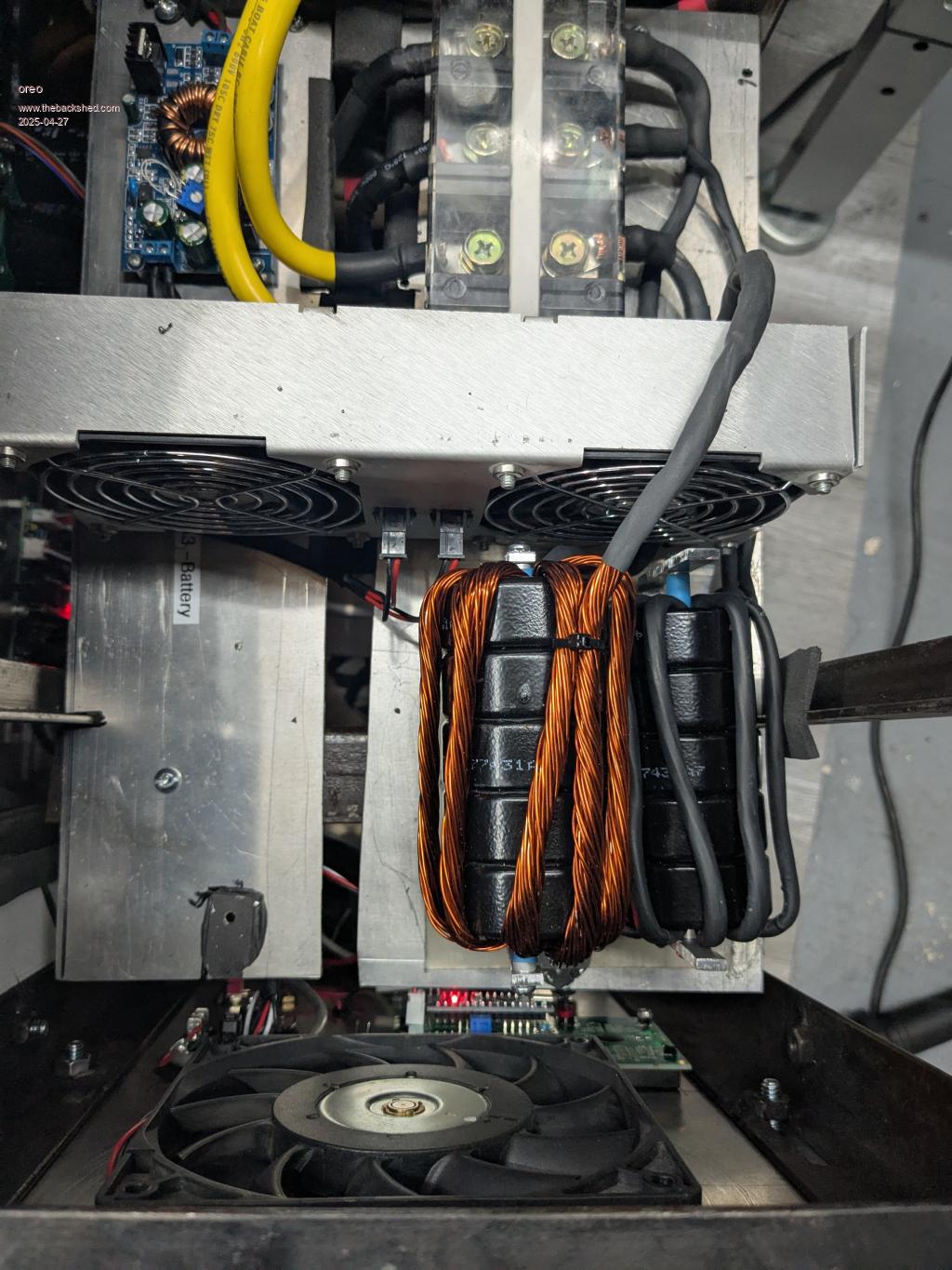 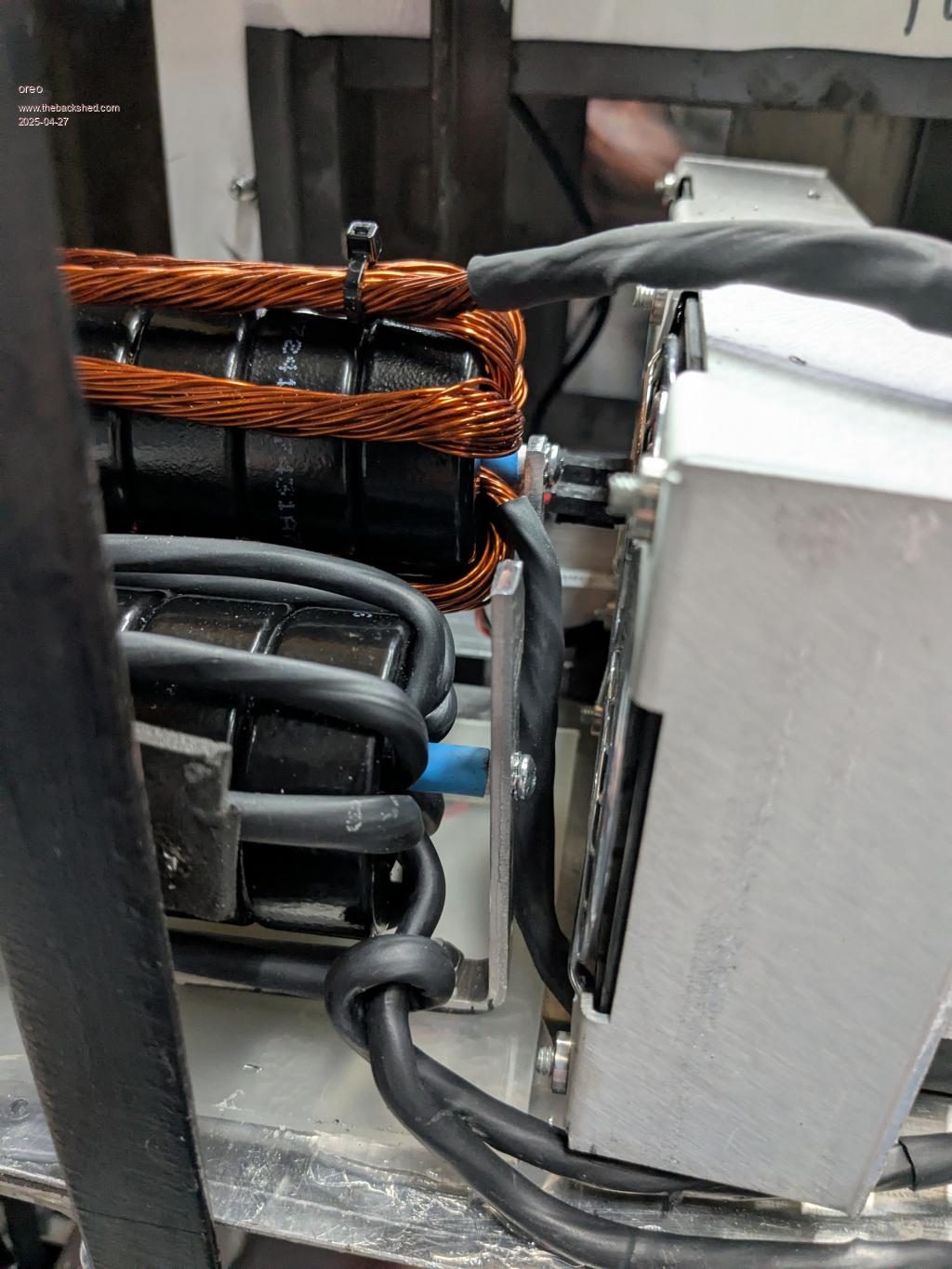 If you're looking for cores, I would try ordering the larger size (Kool Mu=Sendust) from this same vendor. If they ship you the wrong one you can request a refund, otherwise you may get the desired size at a good price! Greg |
||||
| analog8484 Senior Member Joined: 11/11/2021 Location: United StatesPosts: 204 |
Did the same noise oscillation happen with 2 sets of the same cores? Wow ... they are cheap. I may have to get some  |
||||
| oreo Senior Member Joined: 11/12/2020 Location: CanadaPosts: 133 |
Yes it does. I now have the inverter cabinet sealed up and the noise is less noticeable. I am surprised with how quickly the transformer heats up, when you have a decent load on it. With about 5kw out, the fans appear to hold the transformer temp steady at about 56C. The batteries don't last a long time with 5kw out though. Next step is to complete the second transformer and inductors, but no big rush for this. At least I have my work space back. 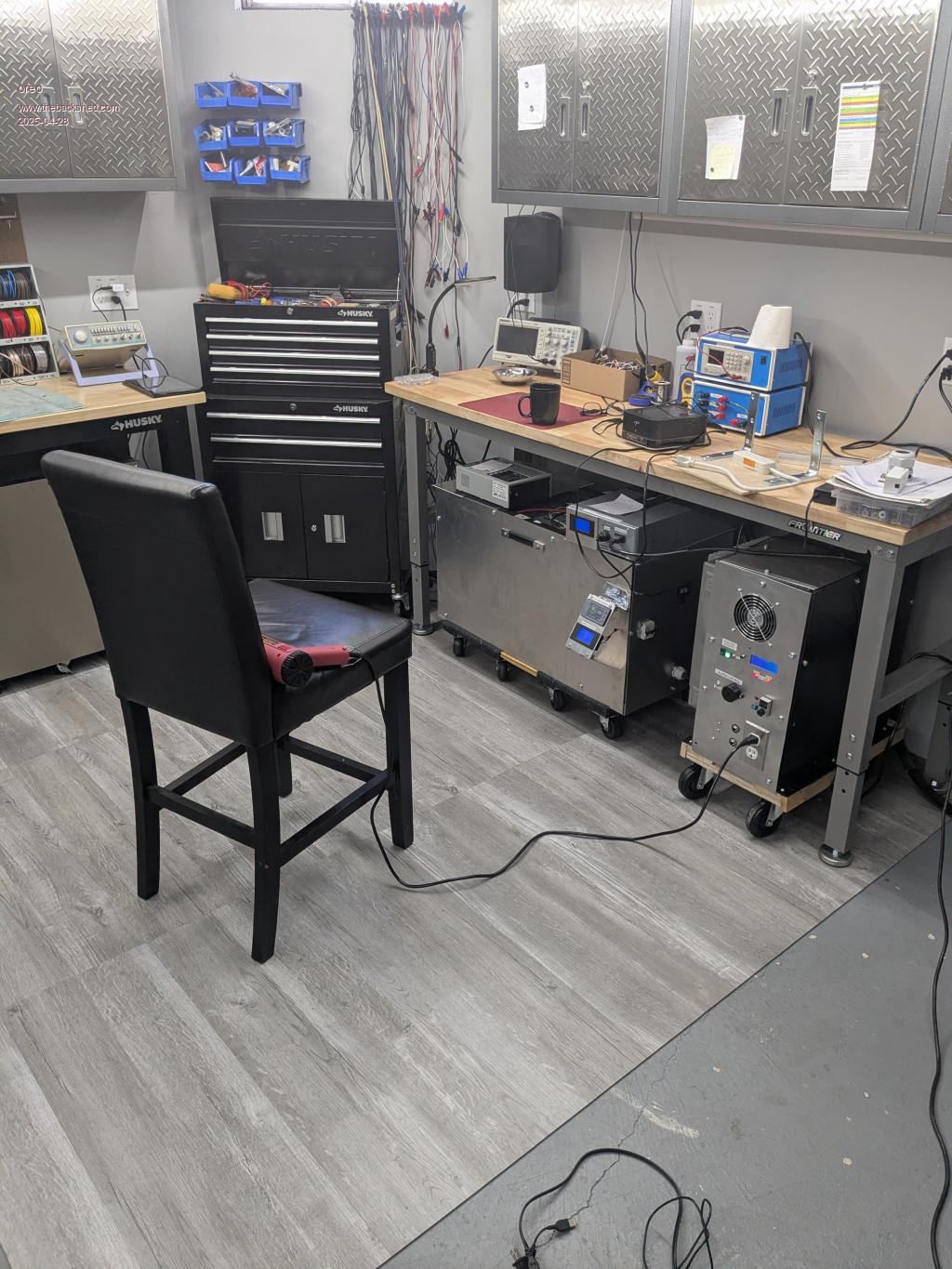 Greg |
||||
| KeepIS Guru Joined: 13/10/2014 Location: AustraliaPosts: 2197 |
This effect is independent of Toriods and chokes. I feel it's inherent in the overall AC regulation FB control with the Nano, as almost any load stops the effect. No, I'm not going to look into, I can visualize this with an unloaded floating secondary and NANO ACV FB, and it's of zero consequence. BTW: The first time I fired up my Dual Inverter (2 x Toriods, 4 Chokes and 2 power boards) and paralleled the Toroid AC outputs, I joined one side of the AC outputs, then placed a LED (no resistor) between the other paralleled side - I was taking no chances, the LED volunteered to DIE for the cause. The LED slightly glowed each time the DC input voltage was raised, once AC regulation was reached, the LED showed that "roughly" 1Hz very slight glow and fade with an unloaded regulated AC output. FYI The LED lived  NANO:Inverter V 8.2ks - Linux AvrDude GUI script V4.1 |
||||
| KeepIS Guru Joined: 13/10/2014 Location: AustraliaPosts: 2197 |
Look great  I know what you mean about getting bench space back. I know what you mean about getting bench space back.FYI I'm going to post an updated revision of my findings with Toroid heating on my thread, I don't want to pollute your thread with my crap, but this is the result of living with 4 Inverter builds and finally getting the attempt in the third build absolutely right in the Last build. BTW Two Toriods = half the heat = easier to keep cool  NANO:Inverter V 8.2ks - Linux AvrDude GUI script V4.1 |
||||
| analog8484 Senior Member Joined: 11/11/2021 Location: United StatesPosts: 204 |
It certainly seems plausible that there is some steady-state error in the control loop. Good test. I might have missed this in your extensive posts but did the idle consumption fluctuate significantly with the 1Hz "noise" like Oreo's case? |
||||
| analog8484 Senior Member Joined: 11/11/2021 Location: United StatesPosts: 204 |
Nice setup. For clarification, you ran 5kW on one "1500VA" transformer? |
||||
| nickskethisniks Guru Joined: 17/10/2017 Location: BelgiumPosts: 481 |
2 points, how did you mount the mosfets? I'm trying to have a good clearence between bolts and pcb itself, I'm using some standard nylon isolation bushes, they just fit between the pcb and the bolt. The M3 bolts are connected with the heatsink and a short between the positive and negative rail on the pcb is not that difficult to make I noticed. Second point of interest is the way you fixed your inductors, make sure you don't make a short winding, it looks like a short to me at the moment, so you are bypassing your inductance, I could be wrong if the mounting rod/bolt is not going all the way through your inductor or is interrupted elsewhere. For the rest I really like your build, looks verry neat and professional.  Edited 2025-04-29 07:19 by nickskethisniks |
||||
| KeepIS Guru Joined: 13/10/2014 Location: AustraliaPosts: 2197 |
Good pickup by nickskethisniks, if that is indeed a full metal rod through the center of the Choke then the metal bracket at each end completes a full shorted turn ? NANO:Inverter V 8.2ks - Linux AvrDude GUI script V4.1 |
||||
| KeepIS Guru Joined: 13/10/2014 Location: AustraliaPosts: 2197 |
When you think about a bare LED with a slight glow every second or so, and it's the link between fully bridging 6 cores of two toroids in parallel, each expected to "hopefully" have 240Vac on their secondaries, that's good enough for me. I know, very non technical  Idle current is build dependent in this case. IMHO any time a Toriod makes a noise it usually means something is disturbing Toriod harmony, so current will likely rise above normal state. I remember that the Test Bench Current Meter was the first thing I looked it, and I recall that it was very low under 20mA range. I found some of my old postings: It only took a 10W load to eliminate the effect in the unloaded Inverter. In this final build, I happen to have a constant 12W load from Assisted low speed Convection Air Flow using two AC fans, one below each Toroid. The Inverter is silent 99.9% of the time, dumping 16kW of load on the AC output does cause a momentary "very low" hum (you must tenderly hug the inverter to hear it) this quickly fades as the equipment Startup Surge diminishes, that's about it. . NANO:Inverter V 8.2ks - Linux AvrDude GUI script V4.1 |
||||
| oreo Senior Member Joined: 11/12/2020 Location: CanadaPosts: 133 |
Hi Point 1 -I am using these shoulder washers. They fit entirely though the pcb and fully isolate the screw from the pcb (I had to drill out the pcb slightly to get them to fit though) Does that answer your question? Point 2 -If you look closely at the pictures, the core mounting brackets are on plastic (nylon). This isolates them. Now actually I initially missed this and had them mounted to the aluminum chassis which resulted in them being shorted out. My standby current was .45amps, which made me realize my mistake. And thank you for your positive comments! Thanks man. Well for the transformer I basically connected the original primary and secondary in parallel and called that my HV winding, and then added a new LV winding. So that kind of makes the transformer into a 3KVA transformer. (other 3KVA transformers are very similar in weight to my rewound transformer) IMO cooling makes a big difference, and I am passing air through the center of the core, and forcing it closely to the walls of the transformer. Plus the fans I am using move a lot of air and the LV winding has very thin insulation on it which should result in better heat transfer. Further testing is probably in order though. Greg |
||||
| oreo Senior Member Joined: 11/12/2020 Location: CanadaPosts: 133 |
So let me preface this post with me saying how much I like this new inverter and how fortunate I feel to have been allowed to share in the fruits of others peoples labour. I understand that as a DIY project and the results of different builds are going to be different. I am happy with the results of my build. Having said that, I need to set things straight. The noise I am seeing is not on a 1hz cycle, but closer to .1Hz. There also seems to be a misconception that this noise only happens when there is no load. So I made a video and put it in a drop box which you should be able to access here. The testing was done with no load, and a single 1500w resistive load across 240v (turn your devices volume to max) Two other items of note. 1. When I set the inverter to 50hz, I waited for 15 minutes at idle, and did not hear/see any fluctuations in noise or current. The power was higher, sitting at about 20w continuous. At 60hz, the noise started fluctuating after about a minute or so of power up. 2. I was unable to set the output voltage below 243v. I had to change R8 to 62K in order to get the trimmer to get me down to 240v. I double checked all the components surrounding U1 and U2 and they appear to be correct, although I didn't actually measure the capacitors. I just got some new Nano boards in, so I will try one of them to see if that makes any difference. Greg |
||||
| KeepIS Guru Joined: 13/10/2014 Location: AustraliaPosts: 2197 |
Thanks for the video, that is different, I remember a few posts about this on different Inverters, hopefully someone on here will remember. I've never had that on my Inverters. Regulation under a resistive load is not quite right. NANO:Inverter V 8.2ks - Linux AvrDude GUI script V4.1 |
||||
| The Back Shed's forum code is written, and hosted, in Australia. | © JAQ Software 2026 |
