
|
|
Forum Index : Microcontroller and PC projects : PicoGAME HDMI - a natural progression
| Author | Message | ||||
| Mixtel90 Guru Joined: 05/10/2019 Location: United KingdomPosts: 8911 |
Things are progressing. I got the saw out today and this is the result of a "dry run". Only the HDMI socket, SMD resistors, USB-TTL module and USB hub are soldered in - I'm waiting for bits. 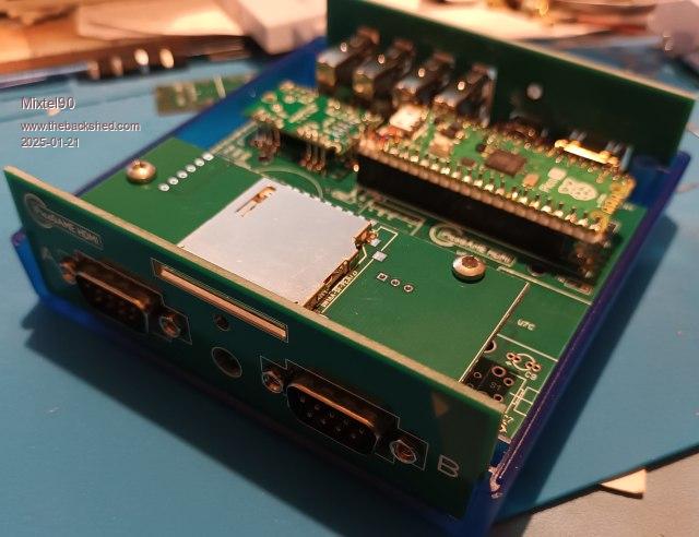 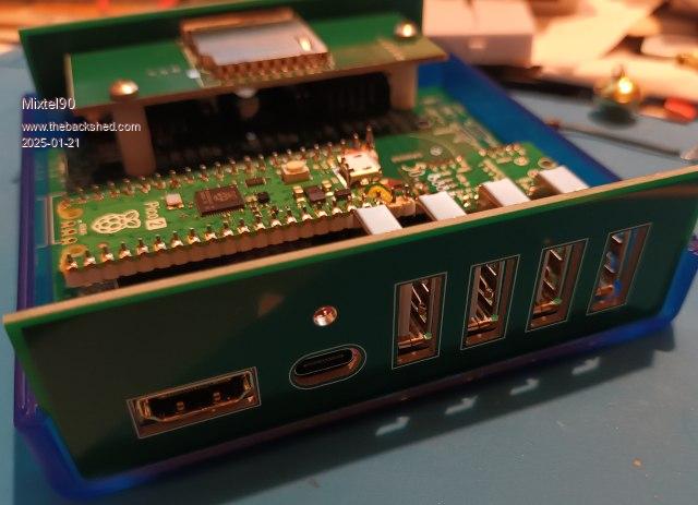 The front panel seems to be *just* a touch too high, but that might be my admittedly inaccurate sawing. It's nothing that a touch with a file won't fix. Even the skinny board for the Reset button on the back seems to fit properly, although the hole may need to be filed just a touch. I can't be certain as I've only fixed the board at one end (over the USB sockets). Mick Zilog Inside! nascom.info for Nascom & Gemini Preliminary MMBasic docs & my PCB designs |
||||
| Volhout Guru Joined: 05/03/2018 Location: NetherlandsPosts: 5934 |
Hi Mick, I finally got the last parts. And the board is running now. Just played PETSCII robots on my large TV. A wireless mouse also works. Still a lot to test, but the basics are running. Really curious about the other screen resolutions, and "mode 3". One thing needed me to fetch the user manual. The text on the bottom of the board shows all options. But there was no OPTION HDMI 5,2,7,0 in 6.00.01. It was called OPTION HDMI PINS 5,2,7,0 I am happy that I finally have a 2350 HDMI board. Now I need to build the box and saw the other boards. Thanks, Volhout PicomiteVGA PETSCII ROBOTS |
||||
| Mixtel90 Guru Joined: 05/10/2019 Location: United KingdomPosts: 8911 |
I spotted the PINS today when I started testing mine. :) In fact, I totally screwed up at first because I loaded the VGA firmware! At the moment I have a problem with USB (only 1 socket working, which just happens to be the keyboard). I suspect that the module might be damaged because it's the one that I pulled off Alpha. It didn't want to come off so I was probably a bit more vicious with it than I should have been. Mick Zilog Inside! nascom.info for Nascom & Gemini Preliminary MMBasic docs & my PCB designs |
||||
| Mixtel90 Guru Joined: 05/10/2019 Location: United KingdomPosts: 8911 |
Up and running so far. The USB problem was a couple of dodgy solder joints. I've decided that I don't like that method of of mounting the USB hub very much, it'll probably plug into 2mm headers next time. I've had the full complement of keyboard, mouse and two generic controllers on it. I'm quite impressed by the audio from that 12-bit DAC. There is enough output to drive my 64R headphones to just over a comfortable volume for me, making PLAY VOLUME useful. I'm not impressed by the rear Reset button as it doesn't quite line up with the hole in the rear panel. Still, it was just squeezed into the gap left on the 100x100 PCB and it should have been deeper really. I installed MMBasic in the intended way, without needing to unplug the Pico. It works well, and the DIP switches are a lot easier than links when I'm short of PCB area. The daughter board with the full size SD card socket and LED is something else that I like. *There is a PCB error!* The SD card socket GND pins are floating. Easily fixed with a link from pin 6 to the GND pin towards the rear of the daughter board. This will be fixed at the next release. The fact that everything fits into the case is a bonus. :) --------- Still not tested the HDMI other than seeing the default screen. Still haven't tested the controller ports either. If you use 1K for the red LED and 1K5 for the green one you get a nice alternating flash of green/orange for the heartbeat. :) Mick Zilog Inside! nascom.info for Nascom & Gemini Preliminary MMBasic docs & my PCB designs |
||||
| Mixtel90 Guru Joined: 05/10/2019 Location: United KingdomPosts: 8911 |
A revised manual with more photos, including some of the completed unit. It now explains the mounting technique for the USB hub module much better. manual11.pdf I never did bother to sort out the reset button position, hence the pen mark on the rear panel. :) . Edited 2025-02-21 20:43 by Mixtel90 Mick Zilog Inside! nascom.info for Nascom & Gemini Preliminary MMBasic docs & my PCB designs |
||||
| The Back Shed's forum code is written, and hosted, in Australia. | © JAQ Software 2026 |
