
|
|
Forum Index : Electronics : Another three-stack toroidal transformer
| Author | Message | ||||
| FET cemetery Regular Member Joined: 17/04/2024 Location: AustraliaPosts: 74 |
I was thinking more of thermal management, the big transformer starts putting out a bit of heat once it's been charging the car for a few hours. What you say makes sense though, keep the chokes in the metal box close to the Fet board so the choke leads are short to minimise RFI. Interestingly, the clamp meter shows several Amps AC on the DC leads to any of my inverters under load, the ripple currents must be significant. No stone unturned, no FET unburned. |
||||
| KeepIS Guru Joined: 13/10/2014 Location: AustraliaPosts: 2142 |
I can have over 700A 100Hz DC positive going "almost sinewave" currents with some workshop equipment. So yes, there are some serious Inverter power board SPWM generating switching currents on the DC cables. The nice thing with toroids is they generally contain their magnetic fields and don't really radiate that much, the power boards are fine close to the Toroids and chokes, considering the power board copper buses and FETS are carrying the same DC SPWM modulation current. In my Dual unit, thermal management is assisted convection flow via two large quality low speed whisper quite fans below each toroid, 240vac fans in series with 120vac across each. they gently move air through AND around the Toroids. The toroids run slightly above room temperature until I'm above 7kW then the fans switch to full speed occasionally, fans switch from series to parallel and run at 240vac for full speed, this holds the Toroids below 40°C to 45°C unless I'm really pushing it. The Toroid housing in the case has quite large strategically placed vent holes allowing natural and assisted air flow over the chokes as well, the chokes also run just above room temperature, the Inverter is virtually silent even at full speed airflow . Edited 2025-04-17 16:38 by KeepIS NANO:Inverter V 8.2ks - Linux AvrDude GUI script V4.1 |
||||
| FET cemetery Regular Member Joined: 17/04/2024 Location: AustraliaPosts: 74 |
With the car charging at 14A the dc current into the inverter is about 70A. Switching the clamp meter to AC it reads just over 40A, I guess this means the inverter DC current is a 100Hz sine-ish wave with a peak at 110A or so and a trough at 30A in this case. Interesting. The battery current is about 5A DC (charging) with an AC reading of just under 40A, so the battery must be seeing a sine wave with a trough at -35A and a peak at +45A, ie it's seeing a fairly hefty 100Hz charge / discharge. I had never really thought this through before, just assumed DC was DC at the battery. Does this sort of micro cycling actively harm a battery? Not that there's anything to be done about it. No stone unturned, no FET unburned. |
||||
| KeepIS Guru Joined: 13/10/2014 Location: AustraliaPosts: 2142 |
This is the normal world of DC when driving any switching device like an Inverter, batteries of all types get battery specific charge/discharge lifetimes if operated within the specified current and temperature Charge/Discharge parameters. NANO:Inverter V 8.2ks - Linux AvrDude GUI script V4.1 |
||||
| FET cemetery Regular Member Joined: 17/04/2024 Location: AustraliaPosts: 74 |
I guess with a traction battery in "normal" use it's seeing all the ripple / noise from pwm motor drives etc but it's all in one direction, discharge. Then when it's charging it's all the other way with whatever ripple comes from the charger. Off-grid doesn't have that clear distinction between charging and discharging. Some progress, things are looking promising: 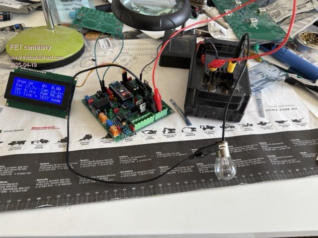 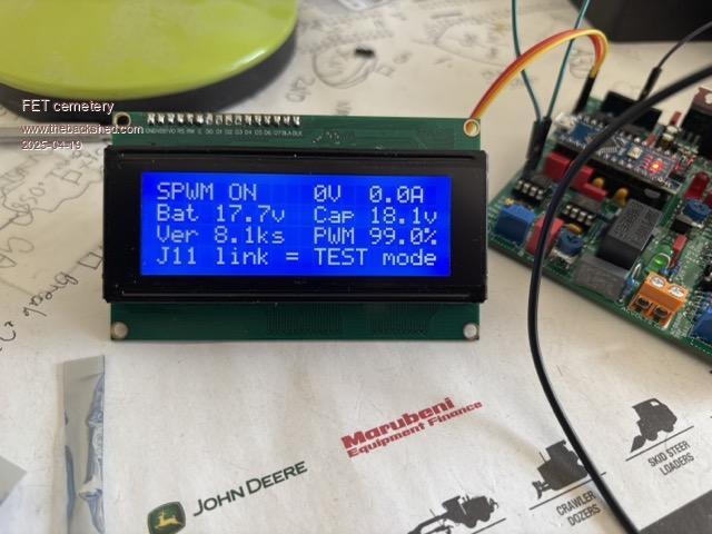 I have 2 boards completed to this stage and the power fet boards are well underway. No stone unturned, no FET unburned. |
||||
| KeepIS Guru Joined: 13/10/2014 Location: AustraliaPosts: 2142 |
The boards are really nice and usually work first go if you are not burning the candle at both ends when building them, which I have done on occasion. I've built a lot of early version boards as Wiseguy perfected his design and more features were added as the wish list grew with each revision, really nice layout now. And they really look the part as well  NANO:Inverter V 8.2ks - Linux AvrDude GUI script V4.1 |
||||
| FET cemetery Regular Member Joined: 17/04/2024 Location: AustraliaPosts: 74 |
Agreed, this is probably the most complex electronic assembly I've done and it's gone together really well (I hope!). The boards are really good for soldering even with my eyes, I just limit myself to a couple of hours a day. A couple of things nearly caught me out: Tantalum capacitors have a polarity, there's a little + sign that needs a magnifying glass to see and they're slightly asymmetrical. I nearly mistook the K for the diode symbol with the zeners on the power board and they almost went in backwards. Cross checking with the BOM and circuit diagram saved me in both cases but it was a near thing! I also force myself to check device pinouts even where they're exactly what's specified. No stone unturned, no FET unburned. |
||||
| KeepIS Guru Joined: 13/10/2014 Location: AustraliaPosts: 2142 |
I do the same with every device, using a small auto detect device with colour LCD screen, shows pin out, device type and polarity, I also check every resistor and cap as my parts bins sometimes have things put back incorrectly, by me  I and a few others have had the same trouble with the zeners and mistaking the K on the PCB. It's good to keep pointing this out as you have done, helps new builders to know what to look out for  NANO:Inverter V 8.2ks - Linux AvrDude GUI script V4.1 |
||||
| wiseguy Guru Joined: 21/06/2018 Location: AustraliaPosts: 1286 |
Ok I hear you all loud and clear - the K is not present for the current Rev3 PCBs. In the previous Rev 2 with the vertical parts I included the letters A & K on the footprint to avoid confusion - but it served well to just add confusion as the A was ignored. Because the letter K was printed in the extended long wire of the vertical part and so symmetrical it caused an unintended issue, in hind sight I could have turned the letter K into a full diode symbol with a small stroke, rotated it to aim the right way and left the A off resulting in no confusion!! Ah well you live and learn.... Sorry for all the headaches this caused! Edited 2025-04-19 19:30 by wiseguy If at first you dont succeed, I suggest you avoid sky diving.... Cheers Mike |
||||
| FET cemetery Regular Member Joined: 17/04/2024 Location: AustraliaPosts: 74 |
If the A hadn't been there the zeners would probably be in backwards now. It was just enough to tickle my old brain cells in to double checking. No stone unturned, no FET unburned. |
||||
| FET cemetery Regular Member Joined: 17/04/2024 Location: AustraliaPosts: 74 |
Just to be perfectly clear, I'm not even hinting at complaining! I still struggle to believe that all this design work has been volunteered. No stone unturned, no FET unburned. |
||||
Revlac Guru Joined: 31/12/2016 Location: AustraliaPosts: 1262 |
No headache for me, you know I had fun with it and learnt a bit more along the way.  Cheers Aaron Off The Grid |
||||
| analog8484 Senior Member Joined: 11/11/2021 Location: United StatesPosts: 200 |
Interesting, can you share the number and specs/brand of the caps used? IIRC, you only used a handful of caps with no issues, so I am wondering what are the cap ripple current (@100Hz) and dissipation factor/ESR ratings. Have you ever measured the cap temp under a significant continuous load? |
||||
| KeepIS Guru Joined: 13/10/2014 Location: AustraliaPosts: 2142 |
Fortunately, very high current duration is usually under 2 or 3 seconds. Capacitors are KERMET 10000uF 63V large Screw Terminals with good ripple current, 80mm x 30mm case, I can't remember if I posted the Specs in the threads. I have checked for heating under sustained 8kW loads for 30 minutes, 1 x 10000uF Cap on each Cap bank will get warm to touch (still way under limits), with two Caps, a slight feeling of warmth, with 3 Caps per Cap board no indication of heat. BTW, NO air flow over the Caps in the tests, and with a "Single power Board" Inverter. In the Dual Inverter, 8kW of LOAD is split between two Power boards, I currently have 3 Caps per "Power Board", for a total of 60000uF in the Dual Inverter. I really only need 1 x 10000uF per "Cap board" on each power board, so 20000uF per Power board for a total of 40000uF in the Dual Inverter. The 3rd cap was included when testing those 700A startup DC currents under various values of Capacitance and a DSO, it was almost impossible to see any difference in any waveforms. NANO:Inverter V 8.2ks - Linux AvrDude GUI script V4.1 |
||||
| FET cemetery Regular Member Joined: 17/04/2024 Location: AustraliaPosts: 74 |
OK so I've been thinking (dangerous) about the nasty AC loading on my poor innocent forklift battery when the car is charging, and wondering if anything could be done to reduce it. Would it be possible to code for the sync input on the WG boards to have a 120 or 240 degree phase offset? 3 phase would reduce that AC to a small ripple. Just a thought! (Assuming they work I will soon have 2 sets of inverter boards. It would be easy enough to assemble another and then wind some more transformers and chokes. Ok, maybe not easy...) No stone unturned, no FET unburned. |
||||
| KeepIS Guru Joined: 13/10/2014 Location: AustraliaPosts: 2142 |
If you search the forums here, there are a lot of off-grid guys who have been using Forklift batteries for many years, you might be overthinking this a bit, as we have all done, and looking for a perceived battery issue that in reality, does not exist. NANO:Inverter V 8.2ks - Linux AvrDude GUI script V4.1 |
||||
| FET cemetery Regular Member Joined: 17/04/2024 Location: AustraliaPosts: 74 |
I know, I guess I'm slightly concerned that charging the car at 5 or 6kW for hours per day might be a bit detrimental but it's not something I lose sleep over. Overall charge / discharge parameters are much more important. The forklift battery is much beefier than the T105's that lasted us 8 years. Off-grid 3 phase would be kind of nice, a cheap VFD would be the sensible option though. No stone unturned, no FET unburned. |
||||
| Godoh Guru Joined: 26/09/2020 Location: AustraliaPosts: 656 |
the Ac readings you are getting on a clamp meter may not be anything to be concerned about. First remember that the battery is also basically a very large capacitor, Ripples will be smoothed out quite well. Really you need to be looking at the leads with a scope to see what sort of ripple you have. It will depend on what sort of clamp meter you have what readings you get on AC when Dc is flowing. I charge our car at up to 5.5 kw on a 24 volt system. But most of the heavy lifting is being done by two GTI inverters that are AC coupled. It is much easier on the battery inverter and the batteries the way I see it. pete |
||||
| Godoh Guru Joined: 26/09/2020 Location: AustraliaPosts: 656 |
I just went and checked my clamp meter on my battery leads. When I checked we were drawing 3.5 amps DC, on AC amps it measured slightly less. I am guessing that the hall effect transducer in the meters does not really mind,. The meter probably just converts the output from the transducer to either an RMS reading or an Average reading. pete |
||||
| FET cemetery Regular Member Joined: 17/04/2024 Location: AustraliaPosts: 74 |
Thanks Godoh hadn't really considered that it could be just a meaningless reading from a meter that's designed for a 50Hz sinewave with no DC component. If the battery was really seeing massive current swings at 100Hz that would be reflected in the temperature (which is logged) when the car was on charge, and there's nothing beyond a couple of degrees in the morning during bulk charge. I generally don't charge the car until we're close to float, and unless it's a stinking hot day battery temp is pretty stable even with the car charging. No stone unturned, no FET unburned. |
||||
| The Back Shed's forum code is written, and hosted, in Australia. | © JAQ Software 2026 |
