
|
|
Forum Index : Microcontroller and PC projects : Raspberry Pi Monitor doesn't work with PicoMiteHDMI
| Author | Message | ||||
| phil99 Guru Joined: 11/02/2018 Location: AustraliaPosts: 3293 |
It appears likely this is a hardware issue rather than the firmware. The Pico outputs simply can't deliver enough current to reach the voltage required by the RPi monitor. That so many other monitors / TVs work fine is probably due to their ability accept a signal strength that is below specification. Following Jim's advice will reveal if this is the case. Daniel's conclusion seems good to me. Paying a premium for a brand name and getting less than a budget model isn't ideal. Edit. It may be possible to boost the output of the Pico pins by adding a bias resistor from each HDMI pin to Vdd. The bias current would not increase the P-P signal voltage but may lift it to overlap the high / low threshold of the monitor input. Without knowing what the monitor threshold is you would have to experiment with different values. Perhaps start with 1kΩ and work down to a minimum of 330Ω. It may also allow you to reduce the value of the series resistors a little. Edited 2025-02-05 08:48 by phil99 |
||||
| matherp Guru Joined: 11/12/2012 Location: United KingdomPosts: 11522 |
Any decent widescreen monitor will window 4:3 in proper format with round circles - all mine do. I have zero interest in playing with this monitor which is an outlier and clearly c..p |
||||
| Amnesie Guru Joined: 30/06/2020 Location: GermanyPosts: 757 |
@ WhiteWizzard Wow this shows me that you really spent some time on this to get it (somehow) work. I wasn't able to do that. And I returned the monitor, since I am not willing to accept that "premium" money when cheaper china-model (and ALL others) do the job just fine. BUT: Your ideas and work could be helpful if I encounter this problem again (hopefully not). Tomorrow my new Eyoyo 8" China monitor arrives, I am sure this one will handle it fine. I'll report about that  Greetings Daniel |
||||
| Volhout Guru Joined: 05/03/2018 Location: NetherlandsPosts: 5934 |
I am surprized how many of you get HDMI in some form working with flying leads and breadboard wiring. You are indeed lucky. We have discussed the requirements for HDMI earlier in a thread, and when we implement HDMI professionally there is a whole heap of requirements to meet. Trace impedance, trace length matching, differential pairs, uninterrupted ground planes. And then we do eye pattern testing to make sure the differential signals complie. I am not surprized if you have a monitor that does not support the smaller resolutions (640x480) and thus relies on higher data rates, that it does not work at all. Maybe...just maybe.. if you use one of Peters latest PCB's (with a controlled routing on HDMI) it could work. But then again, maybe the RP engineer is right, these low resolutions are simply not supported on that monitor. Nowadays 1080p is normal (2Mpix), the new base level. And the RP2350 cannot do that. Volhout Edited 2025-02-05 17:28 by Volhout PicomiteVGA PETSCII ROBOTS |
||||
| matherp Guru Joined: 11/12/2012 Location: United KingdomPosts: 11522 |
Every monitor needs to support low resolutions to support booting and BIOS. I've pointed the RP engineers at MMbasic so if they are interested (almost certainly not) they could always try it and see. MMBasic uses the code they supply as the HSTX example as its base and they state to use the pinout to match the various commercially available adapters - left hand and right hand? Edited 2025-02-05 18:38 by matherp |
||||
| Mixtel90 Guru Joined: 05/10/2019 Location: United KingdomPosts: 8911 |
I suppose that the argument might be made that the monitor is intended for the Raspberry Pi line, not the Pico. The Pico now has the HSTX but that isn't intended to drive HDMI monitors, it's a high speed parallel output, possibly for things like waveform generation and instrumentation systems. The Pico isn't intended to drive *any* kind of monitors, in fact. It's designed as an embedded controller and it's maximum system clock speed is too low. ;) Mick Zilog Inside! nascom.info for Nascom & Gemini Preliminary MMBasic docs & my PCB designs |
||||
| Volhout Guru Joined: 05/03/2018 Location: NetherlandsPosts: 5934 |
Mick, Yes...and NO. If RP publish a driver for HSTX to drive a HDMI monitor (or DVI monitor) they indicate a possible use for the peripheral. When it does not work with RP suggested monitor, they own a problem. To be solved in documentation, or in a firmware driver update. And honestly, appart from using the HSTX for MIPI interface (LCD's) that is a logical application. Volhout PicomiteVGA PETSCII ROBOTS |
||||
| Mixtel90 Guru Joined: 05/10/2019 Location: United KingdomPosts: 8911 |
But the Pico range can't generate DVI if you keep to the maximum specified clock speed (150MHz). That can only be achieved by clocking it well out of spec so RPi can't possibly ever say that it will work with the new monitor. Additionally the GPIO pins are unable to source enough current to drive a 75R input to a monitor, that also makes it unsuitable for VGA. From the Datasheet: "The maximum frequency for the HSTX clock is 150 MHz, the same as the system clock. With DDR output operation, this is a maximum data rate of 300 Mb/s per pin. " The Pico was never intended to drive any sort of monitor. SPI or CMOS parallel displays, yes, but not monitors. The fact that it can be made to do so even in some cases is a very big bonus. :) . Edited 2025-02-05 20:14 by Mixtel90 Mick Zilog Inside! nascom.info for Nascom & Gemini Preliminary MMBasic docs & my PCB designs |
||||
| WhiteWizzard Guru Joined: 05/04/2013 Location: United KingdomPosts: 2991 |
First of all I need to clarify that the RPi HDMI Monitor has worked with every other source I have supplied it - games consoles, TV sticks, casting modules, and also my laptop set to various resolutions. 100% success. I must also stress that I HAVE had an image from PicoMites set at 1024 (with noise) and at 1280 (with lots of noise) but randomly the image disappears - then sometime it will come back when placing a finger on the Pico pins, but more often not. Resetting Pico will sometime then produce a noisy image again, other times not. Must also stress on a batch of 10 genuine Pico 2s I have had some display at 1024 and others not - all with the same model DVI sock soldered directly to Pico, same firmware version, and same short HDMI lead - but trying various leads made no change. It has been mentioned in various posts that ‘some HDMI monitors/TVs/screens wor, yet others don’t but here is the thing that mystifies me: IF it is a digital signal, why will some displays work and others not? Does anyone actually know for certain what is causing this ‘maybe it will, maybe it won’t’? I personally suspect the drive (in)capability possibly introduced by the 220/270R resistors has a big impact (think Peter also saying these aren’t ideal?) so am looking at introducing an HDMI signal cleaner IC (still researching options). Ultimately looking at a solution that would need volume so can’t just use any old eBay/amazon cheapo Chinese module that won’t be available next week! In the meantime I have tried one HDMI switcher hoping it may have altered things but it wouldn’t even show an image in 1024 mode (but did when Pico connected directly to monitor). Have ordered more just to try eliminate where the cause may be. I am determined to get a solution to this as the PicoMite is just brilliant in every way; and so is this monitor (albeit can’t see a clean & consistent 1280 image) |
||||
| Volhout Guru Joined: 05/03/2018 Location: NetherlandsPosts: 5934 |
Hi Glen, When you are not tired experimenting, there is one thing you could try (I don't have your monitor). For each of the 4 pairs of data lines onthe HDMI connector, make sure you drive the cable with it's intended differential amplitude (85ohm - 115 ohm). This can be achieved as in below drawing. 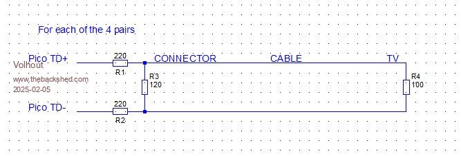 In essence you add a resistor (120 ohm), and replace the 270 ohm resistors with 220 ohm. This change still drives the differential pair with 560mVpp. The minimum for HDMI is 150mVpp, so still lots of margin. Another issue with that monitor could be that the common mode voltage of the pico is too high (with resistors this is 1.65V (3.3V/2)). If that is the case you need to add more components, but the HDMI spec says that 3V common mode is allowed. But maybe this changed in HDMI 2.0 (don't have the standard). Regards, Volhout P.S. another thing important is clock jitter. The HMDI signal has clock embedded in the data (there is no separate clock). The HSTX clock that drives the HSTX block must be jitter free. If you look at PIO, the PIO clock can be programmed to any value. But when your ARM is running 100MHz, and the PIO is programmed to do 99MHz, the frequency of 99MHz is made by running 99 clock cycles of 100MHz, and then skipping 1 cycle. So the clock is not constant. To get a constant clock, the PIO clock must be an integer division of the ARM clock. So 100MHz is fine, 50MHz is fine, 33.33333MHz is fine, 25 MHz is fine. I think this has been taken care of in the SDK (the hard CPUCPEED relation with HDMI resolution), but it is something to be aware of. Edited 2025-02-05 21:07 by Volhout PicomiteVGA PETSCII ROBOTS |
||||
| Mixtel90 Guru Joined: 05/10/2019 Location: United KingdomPosts: 8911 |
Each data/clock loop on HDMI is intended to be 100R. As they are differential outputs from the Pico that puts a load of 100R between GPIO pins, drawing 33mA. That doesn't sound too bad, but there are also biasing resistors that hold each pin at mid voltage under normal conditions and they also have to be overcome. I don't think the value of these is specified but I'd bet on 10K or so. The maximum combined total current for all GPIO pins is 100mA. Obviously, driving four loops at 33mA each is far too much so the current in each loop has to be limited. That means that the voltage across the 100R load in the display has to be reduced and will always be below spec. Due to the internal resistance of the GPIO pins you won't get drive currents as high as those discussed here anyway! The following is hypothetical. Using 270R resistors in the data lines reduces the loop current to about 6mA per loop. The input voltage at the monitor has now dropped from 5V (specification is for 4.3 to 5.3V - you can't officially drive HDMI at 3V3) to 0.6V into 100R. This must surely be marginal. Reducing the resistors to 220R increases the loop current to 7.5mA and the input voltage to 0.75V, which must be an improvement. We are lucky to get DVI/HDMI to work at all. Edit: Thanks, Volhout. I looked for the minimum voltage and couldn't find it. :) . Edited 2025-02-05 21:04 by Mixtel90 Mick Zilog Inside! nascom.info for Nascom & Gemini Preliminary MMBasic docs & my PCB designs |
||||
| Volhout Guru Joined: 05/03/2018 Location: NetherlandsPosts: 5934 |
EDIT: Sorry, HDMI has a separate clock pair. EDIT: and they drive current (source), into 50 ohm pullups (sink). So common mode is 3V. The 120 ohm resitor may not work. Volhout . Edited 2025-02-05 21:24 by Volhout PicomiteVGA PETSCII ROBOTS |
||||
| Mixtel90 Guru Joined: 05/10/2019 Location: United KingdomPosts: 8911 |
I thought they were differential 100R inputs centred at 2V5? I didn't see anything about them being 50R pullups... Mind you, I couldn't find much technical info on HDMI at all! EDIT: Ah, I think I've found it now. Each signal line has a 50R pullup to 3V3, so each differential pair *appears* as a 100R loop. Ideally this is driven by open-collector/drain outputs from the transmitter. This makes life even more interesting. Minimum voltage swing is 150mV and maximum 800mV across that 50R, I assume, so a minimum current of 3mA and a maximum of 16mA. 220R from the Pico should give about 12-13mA, and 270R about 9mA, I think. That's well within spec. Panic over. :) . Edited 2025-02-05 21:57 by Mixtel90 Mick Zilog Inside! nascom.info for Nascom & Gemini Preliminary MMBasic docs & my PCB designs |
||||
| robert.rozee Guru Joined: 31/12/2012 Location: New ZealandPosts: 2529 |
an interesting discussion  just a note of warning - while we are using HDMI sockets at each end and HDMI cabling in between, the signalling standards are 100% DVI. we should be ignoring what the HDMI specifications say, and following just the DVI specifications. just a note of warning - while we are using HDMI sockets at each end and HDMI cabling in between, the signalling standards are 100% DVI. we should be ignoring what the HDMI specifications say, and following just the DVI specifications.almost certainly, once a monitor realizes that the video signal coming in is DVI it will adapt the input circuitry to specifically suit the DVI specifications. cheers, rob :-) Edited 2025-02-05 22:15 by robert.rozee |
||||
| Volhout Guru Joined: 05/03/2018 Location: NetherlandsPosts: 5934 |
Hi Mick, Glen, I dug through some datasheets of HDMI drivers, and I found that they do output a (roughly) 6mA current in each channel (common mode), and modulate that +/- X mA. The pico interface goes to 0mA on the line that is at Vh. Maybe the monitor input does not like that. I will do a simulation to see what that brings us. But it could be that we just need 2 resistors 622 ohm to ground (datasheet DS34RT5110 Texas Instruments), and 220 in series. Will be continued. Volhout Edited 2025-02-05 22:38 by Volhout PicomiteVGA PETSCII ROBOTS |
||||
| Amnesie Guru Joined: 30/06/2020 Location: GermanyPosts: 757 |
You guys are crazy! I never thought that such an interesting discussion will come up. It may help to understand the problem (in general) better! Greetings Daniel Edited 2025-02-05 22:39 by Amnesie |
||||
| Mixtel90 Guru Joined: 05/10/2019 Location: United KingdomPosts: 8911 |
Rob: As far as I can tell the differences between DVI-D and HDMI, although significant, don't really apply here. As far as the hardware goes the plug is the main difference! HDMI has additional capabilities but they are mostly in the software layer (e.g. DVI doesn't support HDCP encryption or audio). Mick Zilog Inside! nascom.info for Nascom & Gemini Preliminary MMBasic docs & my PCB designs |
||||
| Volhout Guru Joined: 05/03/2018 Location: NetherlandsPosts: 5934 |
Rob, DVI and HDMI are identical in the physical layer. But DVI transports RGB data, and HDMI transports YCrCb data. That is where they differ. Hence the monitor needs to know it is DVI data and not HDMI data. 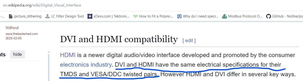 Volhout Edited 2025-02-05 22:47 by Volhout PicomiteVGA PETSCII ROBOTS |
||||
| matherp Guru Joined: 11/12/2012 Location: United KingdomPosts: 11522 |
Can't add to the electrical discussion other than to confirm that all my designs use 220R not 270. On the scope the signals look good especially when looking at the differential signal. |
||||
| Mixtel90 Guru Joined: 05/10/2019 Location: United KingdomPosts: 8911 |
I've tried both values, Peter. Didn't see any difference visually. It probably doesn't matter providing the Pico output doesn't get pulled so far out by the load that the output voltage goes out of spec. The outputs are a bit weedy, especially when you look at the 2350B. Mick Zilog Inside! nascom.info for Nascom & Gemini Preliminary MMBasic docs & my PCB designs |
||||
| The Back Shed's forum code is written, and hosted, in Australia. | © JAQ Software 2026 |
