
|
|
Forum Index : Microcontroller and PC projects : PicoMite HDMI/USB USB Hub Issues
| Author | Message | ||||
| birefringence Newbie Joined: 25/02/2025 Location: GermanyPosts: 23 |
OK, thanks for the confirmation! I removed R54 and, indeed, it finally works. The datasheet says there is an internal pull up OVCUR#, so this is consistent. Now, removing R54 and R55 is quite an easy fix, which I could easily apply to the other four boards I have (after verifying that they do not work otherwise). Given that my SMD reworking capabilities are extremely limited, I'm not sure if there are even any other feasible options. Suggestions welcome  Thanks to everyone involved for all the helpful ideas and suggestions so far! I was somewhat afraid that I was sitting on five broken boards, but now I'm quite confident that I will be able to pass some of them on to others to play with |
||||
| Mixtel90 Guru Joined: 05/10/2019 Location: United KingdomPosts: 8965 |
I'm intrigued as to why other boards have worked and (so far) you have two that didn't. It's obviously something to do with the current limit. Maybe it needs slugging in some way? Mick Zilog Inside! nascom.info for Nascom & Gemini Preliminary MMBasic docs & my PCB designs |
||||
| Volhout Guru Joined: 05/03/2018 Location: NetherlandsPosts: 5994 |
There is a limitted "black out" time between PWREN# and OVCUR#. Q1 should be able to charge C80 in that blackout time. If not...OVCUR# will cut PWREN and disable the 5V wi the USB ports. My guess is that Q1 is not turning on hard with the voltage provided through LED3. This may be mediocre FET's or the wrong type of FET. Even if you can make it work by bypassing R54/R55 you will see that the USB ports cannot deliver enough power for devices (Keyboard/Mice/Game pads) since Q1 is not driven hard. A way to resolve is : replace LED3 with a Si- diode (max is 4.3V). The original LED3 is used as a "level shifter" from a 3.3V output to drive a P-FET at 5V. 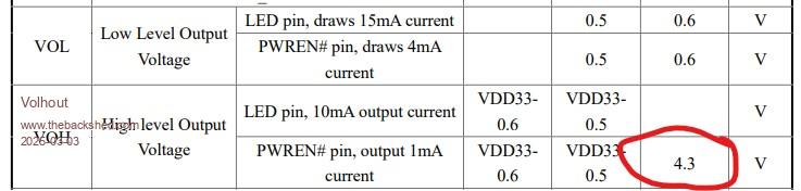 If you inist in having a LED3 function, then place it with it's own series resistor of 4.7K, parallel to R56. Or, replace Q1 with a better part, that turns on hard at the the provided gate voltage. A real MDD2301 should allow 2A drain current at Vgs=2.5V (the 0.7V is for 250uA, which is not enough to charge C80 fast). But if you have 2.5V between gate and source on the MDD2301 that should be fine. Or, maybe change C79 to 100uF (official must be 120uF according USB standard, but 100uF will work also). A smaller value may charge enough in the 334's dead time. Volhout Edited 2025-03-03 22:26 by Volhout PicomiteVGA PETSCII ROBOTS |
||||
| matherp Guru Joined: 11/12/2012 Location: United KingdomPosts: 11646 |
Harm On my board the gate is at -2.7V - 2.3V above ground What about swapping to this mosfet and reducing the capacitor to 100uF? The reason this is important is that Geoff is doing an article for SC on this board and up until now there has been no issue with them working. However, birefringence clearly has an issue and I don't want any builders from the magazine to hit the same thing |
||||
| Volhout Guru Joined: 05/03/2018 Location: NetherlandsPosts: 5994 |
Fet is definitely better. 100uf should be okay. Location of the fuse (fuse is higher impedance than the FET) works in favour, but inviolates overcurrent protection When you have fuse betweeb R54/R55 and usb conmectors, you will not detect the fuse has tripped. In that case it is fine to remove R54/R55 altogether, and overcurrent protection is disabled. Volhout PicomiteVGA PETSCII ROBOTS |
||||
| matherp Guru Joined: 11/12/2012 Location: United KingdomPosts: 11646 |
I'll move the fuse since I have to redo the gerbers - that was a mistake |
||||
| birefringence Newbie Joined: 25/02/2025 Location: GermanyPosts: 23 |
I cannot confirm this. Even on an unmodified board, that I "jumpstarted" by shorting LED3 only for the moment the USB hub becomes active, the over current detection does not trip when I plugin stuff into all 4 USB ports at the same time including my mobile phone, which happily starts charging. This is a transient effect caused by Q1 not switching fast enough. Once it is turned on, everything is fine. Edited 2025-03-04 04:16 by birefringence |
||||
| Mixtel90 Guru Joined: 05/10/2019 Location: United KingdomPosts: 8965 |
How about a small capacitor across R54? Just to momentarily hold up OVRCUR# ? PWREN# is active low, the high level output is immaterial. The 4V3 only leaves 0V7 to turn on LED3 and the mosfet. Not going to happen. VOL is 0.6V max at 4mA. With 0.6V there and 1V8 for LED3 you have 2V6 to turn the mosfet on with. That's going to saturate it fast as you have potentially 4mA to charge the gate capacitance, which is smell. Vds should be less than 200mV at 2A under these conditions. I find it very difficult to believe that this is a mosfet issue. I think it's chip timing. Mick Zilog Inside! nascom.info for Nascom & Gemini Preliminary MMBasic docs & my PCB designs |
||||
| Volhout Guru Joined: 05/03/2018 Location: NetherlandsPosts: 5994 |
Maybe related, maybe not. But the "S1" marking fits to a variety of devices. The envisioned MDD2301 P-FET, or the Si2301 P-FET. And these have different Rds_on. MDD2301  But also:  Specified as:  But WORST CASE it is stuffed with a VISHAY J-FET that has also marking S1.  And that will never work !!! Volhout Edited 2025-03-04 19:47 by Volhout PicomiteVGA PETSCII ROBOTS |
||||
| birefringence Newbie Joined: 25/02/2025 Location: GermanyPosts: 23 |
If I can do more measurements to narrow down the cause, I'll be glad to help. Also, I've dug out a DSO203 mini oscilloscope I purchased quite a long time ago, but have never used before, and managed to get it into a working condition. I tried to capture the switching dynamics, but was not successful so far. I think it should be possible though and I will try again. Also, I can offer to ship the one board that is currently fully assembled and unmodified to someone with better equipment and more experience than me if the situation remains unclear. |
||||
| matherp Guru Joined: 11/12/2012 Location: United KingdomPosts: 11646 |
Unless anyone wants to contradict, the evidence points to the mosfet not switching without help (bridging the led) which suggests the wrong mosfet was fitted since all previous builds have worked without issue. Regardless, I'm changing the design to use a different (better) mosfet with a lower VGS to switch properly. The mosfet I'm proposing is the AP2317A and I will specify this on future builds. I've ordered some of these and will swap them onto one of my boards to check operation. Assuming all OK I could ship some to Germany although it may be easier to order some direct from LCSC. I've just ordered 20 for less than GBP5.00 as I seemed to get free shipping (normally another 5USD. I'll post again once checked but for the cost birefringence you may wish to pre-empt. |
||||
| Volhout Guru Joined: 05/03/2018 Location: NetherlandsPosts: 5994 |
Hi birefrigence, I am willing to analyze it further, and am also to buy the board from you. I have access to better equippment. I am located in Netherlands. But, I think the path taken by Peter should solve the issue (thanks to your help in diagnosing). Let me hear what your plan is, and I can send you my home address in a PM. You can also ship me a board that you have been working on (replacing parts) as long as it has the original S1 FET on it. Volhout PicomiteVGA PETSCII ROBOTS |
||||
| birefringence Newbie Joined: 25/02/2025 Location: GermanyPosts: 23 |
After digging up the DSO203 I just had to play around with it. Now, I'm not so sure if the MOSFET is the problem. It might rather be a faulty CH334F. On the modified board with over current detection disabled, C80 charges within 0.5ms, which I guess is absolutely fine in terms of any timing restrictions. On the unmodified board, however, I don't see any attempt of the CH334F to pull the gate low. It stays high all the time. There isn't even the slightest dip in voltage I can get the scope to trigger on. Also, is it "normal" that it takes about three seconds after the ACTIVE LED turns on until LED3 lights up? (which is what is happening on the modified board) |
||||
| birefringence Newbie Joined: 25/02/2025 Location: GermanyPosts: 23 |
A new batch of Picos has arrived, so I assembled one more board to ensure that it is not a one (or two) off. Again, it shows exactly the same behavior. I studied the CH334F datasheet a little bit more, but could not find anything obvious that would explain all of this. The only thing that makes me a little bit suspicious is that it can be ordered with custom configurations, which could explain why it some chips could be different from others. However, none of the described options struck me as an obvious cause. Just to be clear, for my own personal needs, I'm fine with just removing the two resistors and disable the over current detection. I would, however, be more than happy to donate one of the boards for analysis since I very much like this project and I have received excellent support here. So @Volhout if your offer still stands, and you believe you can maybe gain useful knowledge from it, I would send you one of the assembled and unmodified boards. |
||||
| matherp Guru Joined: 11/12/2012 Location: United KingdomPosts: 11646 |
All: If you have had boards made to my USB reference design with the 4-port hub please PM me the JLC order number for the smd assembly (starts SMT). You can get this from the order history on your JLC account. Please include the order date and whether the hub works properly - thanks |
||||
| jimbotron Regular Member Joined: 27/11/2013 Location: AustraliaPosts: 50 |
Hi Matherp. I also have problems with the USB. Have sent you the order details via PM |
||||
| falcmax Newbie Joined: 15/02/2025 Location: ItalyPosts: 7 |
Hi, On my board I use the same CH334F chip but without the LEDs and without the PWREN circuit. I placed PTCs on the USB 5V line, and everything works fine. I’m attaching a photo of the chip mounted by JLCPCB.   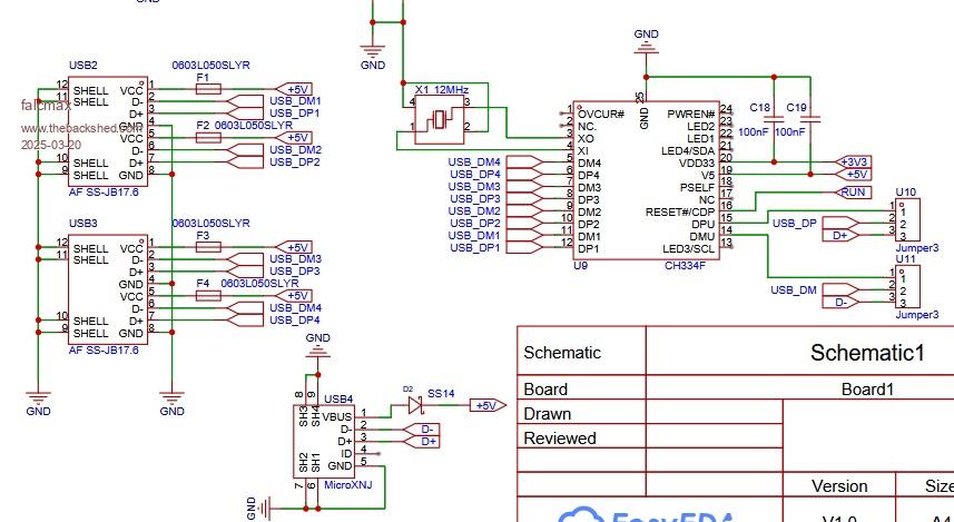 |
||||
| matherp Guru Joined: 11/12/2012 Location: United KingdomPosts: 11646 |
Jimotron You are the only person reporting that the hub didn't work with R54 and R55 removed. Do you have another board you can try with just this mod? Please can you confirm the batch number of the CH334F - probably 13122E20 which are the bad ones. 1163FD43 are the good ones falcmax Why didn't you use the CH334P since you aren't using the LEDs or overcurrent? |
||||
| Volhout Guru Joined: 05/03/2018 Location: NetherlandsPosts: 5994 |
Nice, 8Mbyte DRAM (not PSRAM). Are you using PIO to drive it ? Volhout PicomiteVGA PETSCII ROBOTS |
||||
| falcmax Newbie Joined: 15/02/2025 Location: ItalyPosts: 7 |
When I was designing it on JLCPCB, it wasn’t available, but now I’ve seen that they have some in stock. In any case, I have to redesign the board due the wrong assignement of the I2S signals, so may be I will use the CH334P. |
||||
| The Back Shed's forum code is written, and hosted, in Australia. | © JAQ Software 2026 |
