
|
|
Forum Index : Microcontroller and PC projects : Palm Pico - progress
| Author | Message | ||||
| matherp Guru Joined: 11/12/2012 Location: United KingdomPosts: 11698 |
Thanks The idea is, of course, that it will be completely open source and that when I share everything anyone will be able to make one with no special skills other than a bit of soldering (and getting JLC to make some PCBs). It will run bog standard MMbasic with a single command to configure everything - OPTION RESET PALM PICO I really dislike things that are supposedly open source but need bits that can't be sourced by the average person. There will be nothing in this like that. |
||||
| Friday Newbie Joined: 25/08/2025 Location: United StatesPosts: 10 |
Will the WiFi version for the 2w work as easy? |
||||
TassyJim Guru Joined: 07/08/2011 Location: AustraliaPosts: 6555 |
The board uses the Pimoroni PGA2350 so - No to the PicoW VK7JH MMedit |
||||
| Mixtel90 Guru Joined: 05/10/2019 Location: United KingdomPosts: 8997 |
I ike working with the PGA2350. It's like grass-roots Pico playing but without the hassle of the power supply stuff. It's obviously never going to fit on stripboard though. :) It drops into this sort of project very nicely. It's looking very nice indeed, Peter and I applaud your open source hardware policy. :) Mick Zilog Inside! nascom.info for Nascom & Gemini Preliminary MMBasic docs & my PCB designs |
||||
| Amnesie Guru Joined: 30/06/2020 Location: GermanyPosts: 763 |
I am really curious about this project! But as some of you already mentioned; I also think that it is important that there is some UART or GPIO left to tinker with. Greetings Daniel |
||||
| matherp Guru Joined: 11/12/2012 Location: United KingdomPosts: 11698 |
There is an external port with the system i2c allowing you to connect any i2c device, e,g, a Wii Classic. There are also 8 pins (GP8-GP15) assigned to DB8-DB15 on the display. The user can choose to run the display in 8-bit mode (RGB888) slowest but still fast, 12-bit mode (RGB888) mid-speed, or 16-bit mode (RGB565) blazingly fast. By default the Palm Pico set up will assume 12 bit mode leaving GP12-GP15 unallocated. There are zero ohm resistors in the path to the display on the board which can be omitted in the BOM or removed later depending on the user's preference. DB8-DB15 are connected to a header at the top of the board. Edited 2025-10-05 21:45 by matherp |
||||
| matherp Guru Joined: 11/12/2012 Location: United KingdomPosts: 11698 |
The prototype is now complete. The top and bottom panels have been laser cut out of plastic sheet but I think PCB versions would be better. The final version will be 1.4mm bigger all round to space the screws away from the edge and stop the spacers overlapping. In addition, the keyboard PCB will be extended to be the same width as the screen so that the screws mounting it will line up on the top. The version shown is 33mm deep. This has the keyboard and PGA2350 soldered direct to the motherboard. With them both socketed the depth increases by 3mm. Ergonomically it works well held in the hands with all keys accessible to the British standard thumb. Alternatively, it could sit on a table with rubber feet and be easy to use. I will work on a full manual in the next couple of weeks and publish all the design information needed to build one. Total cost to build including everything will be of the order of USD100 of which USD35 is the 5" SSD1963 IPS screen which IMHO is what makes the device properly usable. Of course the unit is fully supported by standard MMbasic V6.01.00 and is configured with the command OPTION RESET PALM PICO. The unit should be able to run the complete suite of Game*Mite software with minimal changes (keyboard input rather than direct switches) although by running the screen in 8-bit mode GP8-GP15 are freed up for an external gamepad and there is a port for connecting controllers such as the Wii Nunchuck or Wii Classic - perhaps I should make a WII edge connector on the side of the motherboard? As above the battery is a 10000mAh flat pouch cell and should provide 20 hours of use. The red LED is the caps lock indicator. There is a heartbeat LED on the motherboard that can be seen between the various layers to confirm MMbasic is running 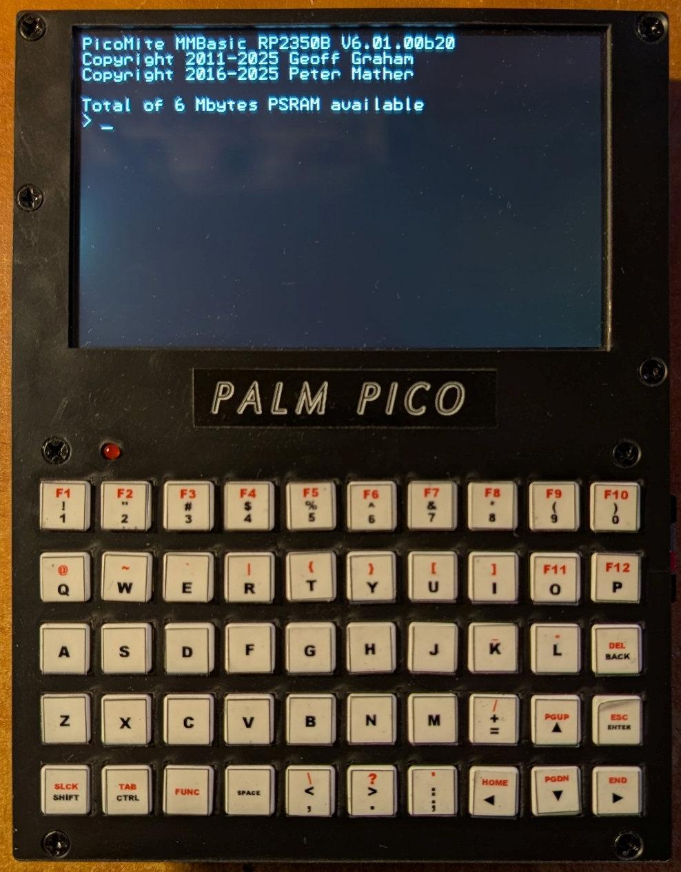 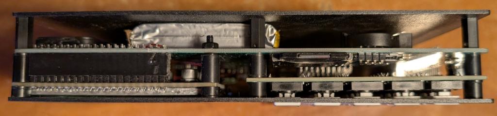 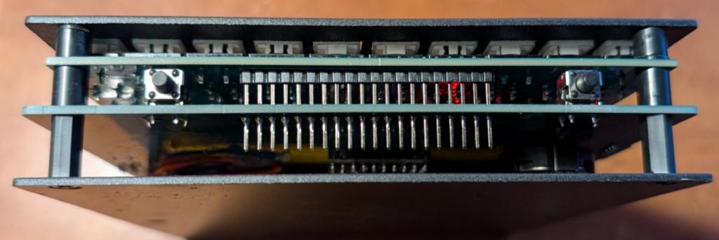 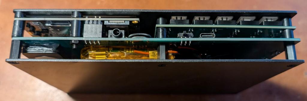 Edited 2025-10-10 04:49 by matherp |
||||
| toml_12953 Guru Joined: 13/02/2015 Location: United StatesPosts: 694 |
Getting close! I'm glad the estimated cost is as low as it is. Thanks for your continued work on this. Will the final version have enclosed sides? Edited 2025-10-10 13:47 by toml_12953 |
||||
| phil99 Guru Joined: 11/02/2018 Location: AustraliaPosts: 3331 |
Previous page:- |
||||
| homa Guru Joined: 05/11/2021 Location: GermanyPosts: 651 |
WOW  Christmas is coming... |
||||
| matherp Guru Joined: 11/12/2012 Location: United KingdomPosts: 11698 |
I decided to do a variant for hand soldering using the usual Aliexpress modules. I'll get one made and see which I think is better. There is just one sot23 because I can't find a sensible through hole replacement for the A03401A p-channel mosfet. Otherwise the only smd parts are 1206 which personally I find much faster and easier than through hole. Schematic f0e8a54f-5b96-429a-a70a-a4ed3b7139db.pdf Layout 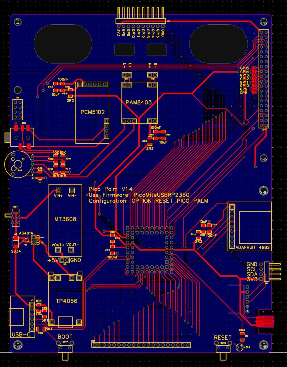 |
||||
| DigitalDreams Regular Member Joined: 03/05/2025 Location: United KingdomPosts: 65 |
Onboard i2c Stemma/Qt connectors please for internal sensors !!! (if there's enough room, larger case option maybe so they can be attached to the inside ?) Currently playing with temp/humidity, magnetometer/accelerometer, DS3231 RTC, and 1Mb fram.... Soon 2Mb fram (stacked), heart rate/blood oxygen, speech, IR send/receive etc. Hence need a free internal i2c connection ?. |
||||
| matherp Guru Joined: 11/12/2012 Location: United KingdomPosts: 11698 |
Why internal and which standard? Do you want the module(s) to fit internally or just have access to the connector? My current sneaky fun plan is a VGA adapter board for the top 8 pin connector that will allow you to plug into a VGA display and duplicate what's on the LCD - may be pipe dreams though  |
||||
| DigitalDreams Regular Member Joined: 03/05/2025 Location: United KingdomPosts: 65 |
Internally sir, can be mounted on the inside of the back case (as I'm doing with a PicoCalc right now). Shame I can't upload a photo here. Using 1.0mm QT/Stemma but happy to make the link cable myself to your motherboard (I see there's four through holes behind your external i2c connector ?). I'm also running a very happy Pico2 at 378Mhz with ceramic heatsink (no shorts if it falls off). Have you tried above 360Mhz with the Pimironi module ?. Also what RTC are you using ?, my DS3231 is currently running at around +0.5 seconds per month and I'm trimming it closer  ... ... |
||||
| matherp Guru Joined: 11/12/2012 Location: United KingdomPosts: 11698 |
DS3231 standard module with the memory chip. I'll add three sets of pads for qt sockets on the bottom of the board 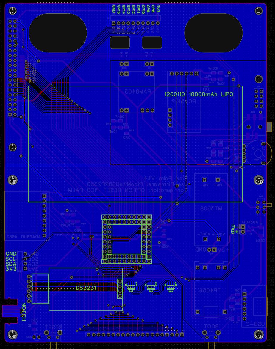 Edited 2025-11-08 21:49 by matherp |
||||
| DigitalDreams Regular Member Joined: 03/05/2025 Location: United KingdomPosts: 65 |
Excellent Peter.... One would do for me (current one in PicoCalc goes to a 5 port extender attached to the back case so only one cable between) but others might prefer more.. How noisy is the keyboard ?, a video perhaps ? |
||||
| Mixtel90 Guru Joined: 05/10/2019 Location: United KingdomPosts: 8997 |
Excellent. :) This looks very much like it would if I was designing a version of it. ;) Unless you are considering a case I'd suggest moving the boot and reset buttons up a bit so that they don't protrude (unless the builder decides to use long button versions). It would be a bit of a pig to hit Reset accidentally. It would also mean that you could stand the completed assembly up on its bottom side. Mick Zilog Inside! nascom.info for Nascom & Gemini Preliminary MMBasic docs & my PCB designs |
||||
| matherp Guru Joined: 11/12/2012 Location: United KingdomPosts: 11698 |
Good idea - will do |
||||
| dddns Guru Joined: 20/09/2024 Location: GermanyPosts: 891 |
Maybe the same for the USC-C socket. Isn't this the place where you grab it and have your hands? edit: I would place it like it's done on mobiles, at the bottom physical forces on the socket is another important aspect I like this design better. This could even be milled, if one of the modules would fail the service is easy. And if the Chinese found a design they usually stick to it for ages. Edited 2025-11-09 08:45 by dddns |
||||
| Mixtel90 Guru Joined: 05/10/2019 Location: United KingdomPosts: 8997 |
With USB-C on the bottom you couldn't leave it on charge while stood up at the back of the table though. I've been playing with plug-in modules for my Multi 2 project. The audio position takes the same I2S module as this, but you can change the firmware and plug in a I2C or PWM (passive only at the moment) module in the same position. Nothing else changes. Likewise the video position, using a carrier board this time, can have HDMI, VGA (with or without palette switch) or LCD touch panel. The modular approach has some advantages, but it can get a bit bulky. :) Mick Zilog Inside! nascom.info for Nascom & Gemini Preliminary MMBasic docs & my PCB designs |
||||
| The Back Shed's forum code is written, and hosted, in Australia. | © JAQ Software 2026 |
