
|
|
Forum Index : Electronics : Recovering from disaster by using Wiseguy's mosfet driver design
| Author | Message | ||||
| tinyt Guru Joined: 12/11/2017 Location: United StatesPosts: 559 |
Measurements are in the inverter at the points shown in red. .jpg) You are probably correct about the waveform distortion with load and without load which affects where the EG8010 is sampling it. It is not the duty cycle I just labeled it spwm, it is the ac voltage reading from the fluke DMM, see figure above. Thanks. It is a rat's nest inside and it is still a work in progress. I am still struggling with the arduino coding for all monitoring and controls. And I also still have to learn how MQTT and Home Assistant work. Edited 2025-10-02 01:15 by tinyt |
||||
| analog8484 Senior Member Joined: 11/11/2021 Location: United StatesPosts: 203 |
Thanks for doing the measurements. So, the main takeaway for me is that it's possible to achieve very high surge power with a relatively small/lightweight transformer core with a little larger winding gauge and a ~2x power stage board. This is encouraging. |
||||
| tinyt Guru Joined: 12/11/2017 Location: United StatesPosts: 559 |
Maybe it also has to do with core material and it being a toroid. I am only guessing, I am just an experimenter. Edited 2025-10-02 03:47 by tinyt |
||||
| KeepIS Guru Joined: 13/10/2014 Location: AustraliaPosts: 2177 |
I was also initially surprised that just a single 2kW AeroSharp Toroid, using the existing 230vac winding and a 27 turn 4-gauge primary winding could easily start large induction motor surge loads, without apparent signs of waveform saturation. Huge loads like the one that blew the FETS in this thread, are obviously going to expose the slightest weak spot in the complete Inverter chain. I mean right from the quality of the sourced components (FETS) to every connection and connector and cable in the DC supply path to the FET terminals. Any hidden instability in layout and any weak point in the AC and filter connections and filter design right up to the Load. And the big one - Choke saturation, should it/they fully saturate, from what I have read, this has the potential to suddenly double (or more) the FET current under these huge surge loads in an Inverter. I have no desire to test this though  _ Edited 2025-10-02 09:30 by KeepIS NANO:Inverter V 8.2ks - Linux AvrDude GUI script V4.1 |
||||
| tinyt Guru Joined: 12/11/2017 Location: United StatesPosts: 559 |
Just an FYI update: The power board is fixed. All 24 mosfets were replaced together with their totem-pole drivers. Two gate drive diode 1N4148 were tested to be shorted and they were also replaced. It is now running and the voltage readings I posted earlier were taken from the inverter with this power board. The soft-start module came and I tested it using a small step-down transformer for the load. Input is grid(mains/street power). The scope probe is at the low voltage section of the transformer. Trimpots on the module were re-adjusted for arbitrary start-up voltage and ramp delay. Edit: Earlier pictures that showed zero crossing anomaly is no longer present with additional heating element load in parallel with the small transformer. Pictures are now replaced. 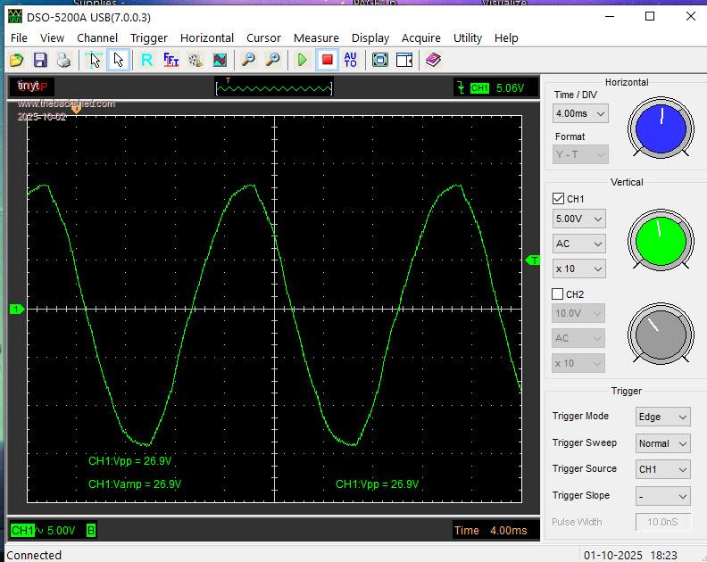   (Output waveform after delay in the first picture shows triac zero crossing discontinuity?) <- No longer relevant. (I think the delayed bypass relay is really needed so that the compressor will not run with this zero crossing anomaly.) <- No longer relevant. Will test it using my small air compressor induction motor later. Edited 2025-10-02 11:40 by tinyt |
||||
| analog8484 Senior Member Joined: 11/11/2021 Location: United StatesPosts: 203 |
That's another good data point. Good point. Tinyt also has quite a few choke cores in his inverter. |
||||
| Boppa Guru Joined: 08/11/2016 Location: AustraliaPosts: 816 |
I think its simply people loading the PowerJacks too hard that causes issues, I made sure I never took mine past about 6kw max (3/4 of its rated continuous max) and mines been running since 2014 part time, and ran from 2018 to earlier this year 24/7... And yeah- that was a 12v 8kw one- pulled about 800-900A occasionally, but happily ran the MIG welder, plasma cutter with the air compressor and even the old stick welder without issue- all highly inductive loads lol (its actually over at the neighbours running his caravan after his 2kva inverter blew up on the microwave- mines been running my microwave for years (I do all my cooking on electric here lol) Only reason it got 'retired' was I am putting the 48v 12kw Sigineer in for the house now... still running and over a decade old at this point....  |
||||
| KeepIS Guru Joined: 13/10/2014 Location: AustraliaPosts: 2177 |
That may be true for the power jack inverters, which were better than a lot of other inverters back then, but have also had their own build and design issues over the years, the choke and the toroid winding compromises being among them. The China Boards like the ones used here are very powerful and a good design. If the correct mods are made to the 8010 and the correct choke is used, they are almost unbreakable. I have run them at extreme power levels @ 24V and 48V, obviously 48V is a little more forgiving when poor wiring and connections are in the DC bus path. These boards usually current trip before letting go, that's providing the DC path is wired correctly with no excessive voltage drop or high current glitches, they are cooled correctly, the choke is the correct inductance and does not saturate before current trip, and the toroid is wound for around 1.0 Tesla, not the typical commercial values around 1.6T. However we don't have control over the FET quality and matching, or the mounting and heatsink interface for each FET in these Inverter boards. Over the years the quality of some of the major components has varied and some are just unlucky to have these components in their inverter. Obviously that's the same situation with the Inverter power boards that we build ourselves, one can only try to order quality components and hope we get them. Pretesting sometimes shows a FET out of spec, in the end, we roll the dice and if it goes splat we have another go. This process is made a lot easier if we know that the Inverter design is robust and proven with no known glitches, therefor any "unexpected" blow up is usually a component quality failure, or we did something wrong in our inverter build. _ Edited 2025-10-12 13:23 by KeepIS NANO:Inverter V 8.2ks - Linux AvrDude GUI script V4.1 |
||||
| tinyt Guru Joined: 12/11/2017 Location: United StatesPosts: 559 |
Just an FYI for those using the EGS002/EG8010 chip. I don't know if others have encountered it, I think it is related to our setup. If the VFB signal is amplitude modulated at low frequency (in my case it is about 10HZ), the EG8010 will set the overvoltage alarm. But visually, it is two flashes, overcurrent, even though IFB is grounded. So we really don't know which one. In the scope capture below, the green trace is at the LEDOUT pin of the EG8010 and the yellow trace is at the VFB pin of the EGS002. It took us a month to narrow it down to this and bypass it. 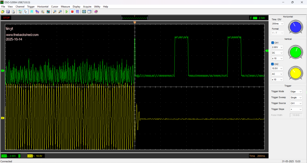 Edited 2025-10-15 01:21 by tinyt |
||||
| The Back Shed's forum code is written, and hosted, in Australia. | © JAQ Software 2026 |
