
|
|
Forum Index : Microcontroller and PC projects : PM Standard - HW Watchdog issue...
| Author | Message | ||||
| Mixtel90 Guru Joined: 05/10/2019 Location: United KingdomPosts: 8911 |
That annoys me about the Zero. :( IIRC it's on the bottom left pad of the Reset button, but it's a bit of a pig to get to. Mick Zilog Inside! nascom.info for Nascom & Gemini Preliminary MMBasic docs & my PCB designs |
||||
Grogster Admin Group Joined: 31/12/2012 Location: New ZealandPosts: 9975 |
Yeah....  Even if they put it on one of the wee pads on the BOTTOM of the module, but nope...  Smoke makes things work. When the smoke gets out, it stops! |
||||
| Mixtel90 Guru Joined: 05/10/2019 Location: United KingdomPosts: 8911 |
mmm... it's my main criticism of the module.I suppose it's something that can be achieved simply by breaking the power rail so it's not the end of the world for most projects. Mick Zilog Inside! nascom.info for Nascom & Gemini Preliminary MMBasic docs & my PCB designs |
||||
| phil99 Guru Joined: 11/02/2018 Location: AustraliaPosts: 3291 |
Re the external watchdog, if you need to save the current of 2 x NE555s (or 556) a pair of CMOS hex Schmidt inverter gates can do a similar job for less cost than the 7555 version. Tomorrow I will have time to test it on a Pico if you are interested. |
||||
| Grogster Admin Group Joined: 31/12/2012 Location: New ZealandPosts: 9975 |
Hey Phil.  Thanks for the offer. IF YOU HAVE TIME, I would be interested in the results, just for a GP external discrete WD circuit. Did you see the standard 555 circuit linked to? That was quite clever, I thought, but MINIMUM power consumption is one of my things, as if the power fails, a backup battery takes over, but with thirsty electronics, that battery won't last long.  Having said all that, I am working on a totally NEW layout for a PCB module, with the same footprint as the WS-Zero, but using the standard MM2 in SSOP. No disrespect to the WS-Zero or the PM codebase, but the standard MM2 code has never let me down, and the issues raised in this thread have made me have a bit of a rethink. If a MM2 module in WS-Zero footprint would be something that the forums would be interested in, I would make all the gerber files available. Smoke makes things work. When the smoke gets out, it stops! |
||||
| Wolfgang Regular Member Joined: 03/11/2021 Location: GermanyPosts: 88 |
Perhaps you can use this module, two of them can produce external resets too https://gleanntronics.ie/en/products/miniature-digital-timer-5v-2s-2h-c005-delay-module-1995.html |
||||
| Volhout Guru Joined: 05/03/2018 Location: NetherlandsPosts: 5931 |
Grogster, You are designing a MM2 in WS-Zero footprint to have a drop in replacement for the WS-Zero in your application ? Just for the watchdog issue ? Or also because of the lower power supply current of the MM2 ? - for the power supply current nothing can be done. pico needs more power. - for the watchdog problem on pico (assuming Peter creates ON ERROR RESTART or ON ERROR GOTO) the recipe is OPTION AUTORUN,NORESET combined with in your program ON ERROR RESTART WATCHDOG HW 8000 That should settle it, right ? Volhout P.S. I actually like the ON ERROR GOTO more, since it also gives you the opportunity to repair the error in a less intrusive way, like RUN... without breaking the USB connection. P.P.S. 555 circuit need minimal 4.5V. Not sure they work at 3.3V. That is why the applications show Arduino (5V) solutions. This may (if you can get an old CD4060, although I think R1 needs to be 1k). 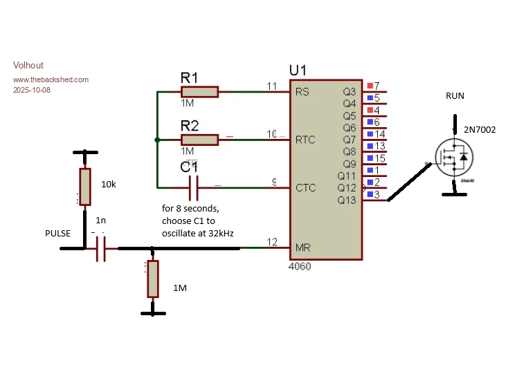 . Edited 2025-10-08 20:39 by Volhout PicomiteVGA PETSCII ROBOTS |
||||
bigmik Guru Joined: 20/06/2011 Location: AustraliaPosts: 2981 |
Hi Grogster, All, Have you actually ascertained that the program has actually crashed and not just whatever code runs the USB port? If for some crazy reason it’s the USB port code (in firmware) that fails and the program is still running it would continue to reset your hardware watchdog.. I think you need to add some code to flash a led to signify if the whole shebang goes belly up or just the USB driver. Regards, Mick (The big one) . Mick's uMite Stuff can be found >>> HERE (Kindly hosted by Dontronics) <<< |
||||
| phil99 Guru Joined: 11/02/2018 Location: AustraliaPosts: 3291 |
Easy to miss in all this but 2/3 down p1 is the answer. |
||||
| ElectroPI Regular Member Joined: 27/04/2012 Location: AustraliaPosts: 42 |
Don't forget there's CMOS versions of the 555 and 556 timers. The ICM7555 works from 2V to 18V with supply current less than 100 microamps. |
||||
| PhenixRising Guru Joined: 07/11/2023 Location: United KingdomPosts: 1960 |
TPS3431: 10µA 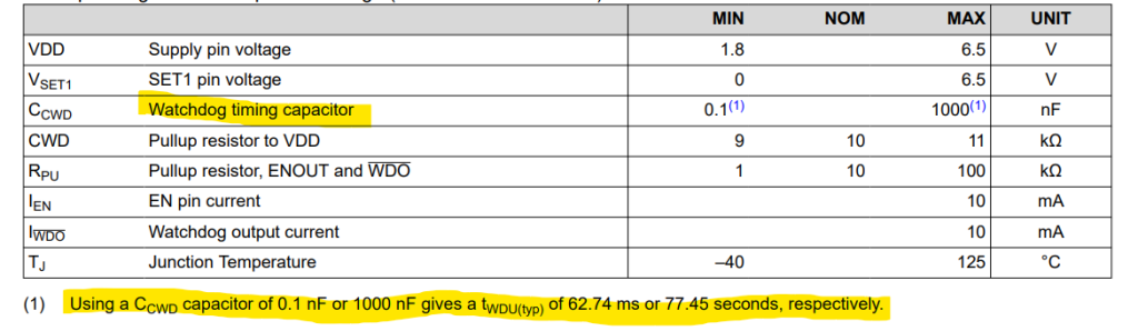 tps3431.pdf |
||||
| Volhout Guru Joined: 05/03/2018 Location: NetherlandsPosts: 5931 |
Analog design.... It won't get any simpler than this one..... 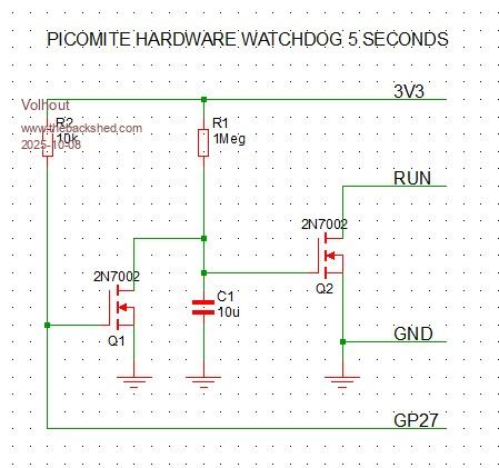 You enable the watchdog with SETPIN GP27,DOUT PIN(GP27)=0 You tickle the watchdog with PULSE GP27,10 '10ms pulse When the time is too short or long, change the 10uF capacitor. The 10k resistor R2 is chosen so even with the bug in the RP2350 IO pins there is always a pullup on the GPxx pin (GP27 in this case). For the RP2040 (the zero) a 1 meg resistor R2 will be sufficient, lowering the current draw significant. Volhout Edited 2025-10-08 22:29 by Volhout PicomiteVGA PETSCII ROBOTS |
||||
| Mixtel90 Guru Joined: 05/10/2019 Location: United KingdomPosts: 8911 |
Oh, that's excellent! It could be tiny using SMD too. Mick Zilog Inside! nascom.info for Nascom & Gemini Preliminary MMBasic docs & my PCB designs |
||||
| Volhout Guru Joined: 05/03/2018 Location: NetherlandsPosts: 5931 |
Mick, It could even fit on a small PCB withing the pins of a zero. The good thing is that you need actively enable the watchdog by setting a GP pin to DOUT. So it won't accidentally kick in. Volhout PicomiteVGA PETSCII ROBOTS |
||||
| Mixtel90 Guru Joined: 05/10/2019 Location: United KingdomPosts: 8911 |
That's one of the things I really like about it. The Pico always has time to boot and the program set up before the watchdog is enabled. Mick Zilog Inside! nascom.info for Nascom & Gemini Preliminary MMBasic docs & my PCB designs |
||||
| phil99 Guru Joined: 11/02/2018 Location: AustraliaPosts: 3291 |
If you replace the MOSFETs with 74HC14 Schmidt inverters Volhout's circuit is almost the same as the one that I was thinking of. The only difference is an input capacitor (used in previous designs in this thread). Without it if the Pico freezes during the pulse the DOUT will stay high preventing the RC from timing out. With it the pulse duration is limited, allowing the RC to trigger a reset in all cases. The catch is adding the capacitor means timing will start as soon as power is applied. |
||||
| Grogster Admin Group Joined: 31/12/2012 Location: New ZealandPosts: 9975 |
For a couple of reasons, actually. I only ever started using the PM, as I kinda HAD to. During COVID, chip shortages were a big issue, and I simply could not buy the 170 MM2 chips from Microchip Direct - they were all out of stock, with lead times of up to a year, and even THAT wasn't guaranteed. So, looking around I found the PM that Peter had recently ported MMBASIC to, so I started using them, as they were cheap and readily available, unlike the Microchip chips. But I decided to just go forward with the PM - why bother to re-invent the wheel, right? But I always preferred the MM2 chip. Now I have quite a few boards out there designed for the WS-Zero module, so in order to avoid having to replace them all(or to hack them to fit an external WD circuit), I came up with the idea of the WS-Zero footprint compatible MM2 module idea. The thing that decided it for me, was discovering no "RUN"/reset pin on the WS-Zero module, so interfacing an external WD circuit requires at least some kind of hack, with a wire to the RESET tact switch. That complicates things, so I though I had enough reason to design a replacement module, which will get me back onto the preferred MM2 chips now I can get them again from Microchip without issue. This also means I don't have to worry about WS stopping production of the Zero module moving forward, which they could do at any time - now I can produce a MM2 module in WS-Zero footprint, that I know I can always build when needed. It seems very likely I will have to visit each of those units to update the software to get around this issue, so if I have to do that anyway, why not just swap the module out for a MM2-based replacement at the same time. That's kinda where my thinking is at this point, anyway. I particularly like your discrete WD timer circuit using just a couple of MOSFETS. I'm tempted to see if I could squeeze that into the WS-Zero footprint module I am working on, but it would be a tight squeeze!  Smoke makes things work. When the smoke gets out, it stops! |
||||
| phil99 Guru Joined: 11/02/2018 Location: AustraliaPosts: 3291 |
Tested watchdog circuit, with some test code. 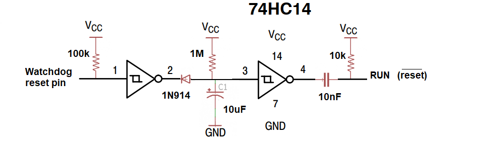 Sub MM.startup Pause 100 Run End Sub Dim integer n=5000 Dim float t0 SetPin gp1,din 'read output of 74HC14 pin 4 SetPin gp0,dout 'intput to 74HC14 pin 1 t0=Timer Print "press any key to exit to console, except Ctrl-C" ' With Ctrl-C the watchdog keeps running, unless you do Pin(gp0)=1 before it resets. Do Inc n,10 If Inkey$<>"" Then 'press any key to exit Pin(gp0)=1 Pause 200 Exit Do EndIf Pause n Print n,Timer-t0,Pin(gp1) Pulse gp0,10 t0=Timer Loop Pin(gp0)=1 End Edited 2025-10-09 15:41 by phil99 |
||||
| Grogster Admin Group Joined: 31/12/2012 Location: New ZealandPosts: 9975 |
Volhout's wee WD circuit - Single layer, 16.5mm x 11.5mm, designed with solder pads, so you can put a bit of double-sided sticky tape on the bottom of the PCB, and stick it anywhere, in pretty much any project.  Can probably shave another mm or so off the width. EDIT: I can. 2mm narrower in width, only 14.5mm x 11.5mm now.  @ phil99: Do you want me to do a wee PCB for your circuit? You can never have too many WD circuits or PCB modules.  Edited 2025-10-09 16:24 by Grogster Smoke makes things work. When the smoke gets out, it stops! |
||||
| phil99 Guru Joined: 11/02/2018 Location: AustraliaPosts: 3291 |
Volhout's is more compact and works in a similar way so there probably is no need. The only difference is at the output end I have added a capacitor and resistor to just pulse the RUN pin rather than hold it low. Holding it low prevents getting back to the console if you try to exit with Ctrl-C. You may want to add a jumper to the PCB to disable the watchdog when testing the main program. |
||||
| The Back Shed's forum code is written, and hosted, in Australia. | © JAQ Software 2026 |
