
|
|
Forum Index : Windmills : Progess photos
| Author | Message | ||||
JimBo911 Senior Member Joined: 26/03/2009 Location: United StatesPosts: 262 |
JarBar I would be happy to send you a copy I have three, have to send one to my folks as well. Jim |
||||
| Gizmo Admin Group Joined: 05/06/2004 Location: AustraliaPosts: 5187 |
Wow Jim. That is good work, and good promotion for the home made renewable power enthusiests ( like us ). Thanks for plugging thebackshed too, much appreciated. A lot of people dont even realise there are web sites out there like thebackshed. If you have a free moment, scan in the article at 300 dpi and email it to me, I'll put it on the web site for all to see. Glenn The best time to plant a tree was twenty years ago, the second best time is right now. JAQ |
||||
| JimBo911 Senior Member Joined: 26/03/2009 Location: United StatesPosts: 262 |
Hello Glen Yeah it's a lot of fun being able to show off ones toys. Here is a link to a news paper add may be you can work with it if not I will scan as you requested. http://www.dailyherald.com/story/?id=322937&src=118 cold and wet here not sure how many people will show up today? Jim |
||||
| JimBo911 Senior Member Joined: 26/03/2009 Location: United StatesPosts: 262 |
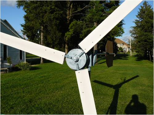
Finally got my mill in the air. Here is a photo of both mills. The mill is not matched very well with my 12 volt system. Still waiting on guys cables and clamps, using ropes right now for support. Now lets get some wind over here asap. Jim |
||||
| JimBo911 Senior Member Joined: 26/03/2009 Location: United StatesPosts: 262 |
Dam forget the photo 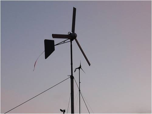
Jim |
||||
fillm Guru Joined: 10/02/2007 Location: AustraliaPosts: 730 |
Hi Jim , Looks like the moment of truth is not far of , looks really good . I found that with the tail streamer it does not give a true indication of the blades being square to the wind , it is better to have the streamers on the guy wire in clean air and look up from the base. My tail is now about 20deg to try and counter balance the blade off set , and have added a aluminium trim to the end of the tail at approx 30deg that seemes to be working well in lighter wind in keeping the blades square to the wind. Hope to see some results soon .. PhillM ...Oz Wind Engineering..Wind Turbine Kits 500W - 5000W ~ F&P Dual Kits ~ GOE222Blades- Voltage Control Parts ------- Tower kits |
||||
| JimBo911 Senior Member Joined: 26/03/2009 Location: United StatesPosts: 262 |
Phill Yeah it's about time I get the mill in the air. It is exciting to watch it spin and track the wind direction. Its only 37 feet up not very high I need to do lots of testing before thinking about raising it any higher. I did notice from your photos you had a fin on your tail I know that Bergy uses this fin arrangement on there tails as well. Thanks for your advice about the tail streamer will make the appropriate changes. Out put of the mill is poor do to the huge mismatch of loading (batteries) my system is still at 12 volts but then I knew this would be the case. I have planed to step up to 48 volts for some time now as soon as my budget will allow I will make the changes. Started working on cap/voltage doubler some time ago but haven't finished it yet been really busy with work. With winter at our door step theirs lots to do around here. Thanks Phill always good to hear from you. Will keep you guys posted. 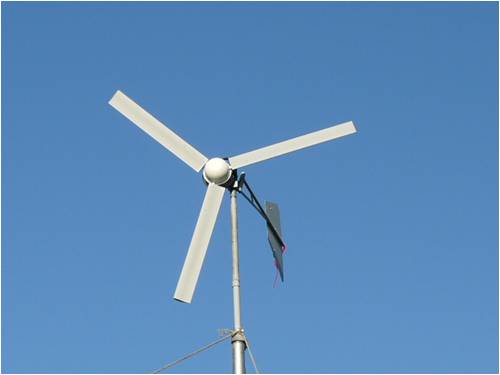
Jim |
||||
| JimBo911 Senior Member Joined: 26/03/2009 Location: United StatesPosts: 262 |
First of all I would again like to thank Glen and all the forum members for helping me on my mill project with out your help and willingness to share and teach I don�t believe I could have accomplished as much as I have. My work (job) has slowed a bit and a bunch of my girlfriends have left me so now I can have some real fun and resume work and or testing on my mill. (OH YEAH) To remind the forum members my mill uses a 60 series 36-pole F&P stator with neo magnets installed in a cast iron drum for the rotor with PVC blades, eight-foot diameter. She has been up and flying for about three weeks now all this time my load voltage has been 12 volts, which I knew was not going to work well. The output has been very low and not much if any use-able wattage. I did manage to build (per Gordon�s specs) and try out a caps/voltage doubler it�s not the prettiest looken thing but what the hell. Keep in mind that I do not profess to be very good at electronics but I do try. The doubler did increase the output but not very much. When I used the voltage doubler it was as if the mill had no load and the blade rpm went way up, after time the caps got HOTT, unable to touch and made a small buzzing sound. I tested the system in both star and delta with not much noticeable difference. 20 or 25 watts was about all she could do in 10 to 15 mph winds. (12-volt load) My goal from the beginning was to jump my system from 12 to 48 volts. I sourced out enough batteries to test the mill at 48 volts. I first used the caps/doubler the output was higher because (I suspect) of the higher voltage, caps stayed cool with no buzzing sound still output was low 50 to 60 watts 10 to 15 mph winds. I then removed the doubler, wired it for delta the output increased a whole bunch at approximately 15 mph winds Doc Wattson read 425 watts, 6.46 amps at 50.35 volts. I am sure she can make more power as I do believe the tail started to furl at 15 mph which of course is to low a wind speed to start furling. I am not sure if I should add weight or increase the tail fin size to push back the furling to a higher blade rpm. I think I am going to have to re balance the blades and rotor cause she likes to oscillate (move back and forth) at around 200 to 250 rpm or so, at higher rpm�s the mill really takes off with no wobble. So far, I have been able to stop the mill very quick with dynamic braking. We have not had any storms in this area so as Phill pointed out (The moment of Truth) has not arrived yet. Anyways there you have it; now it is time to hear from the pros out there so any and all comments are most welcome. Yes I have a smile on my face.  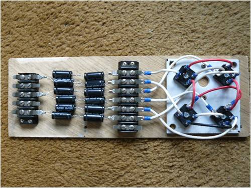
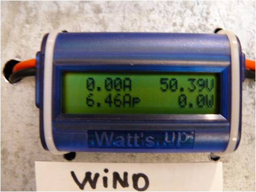
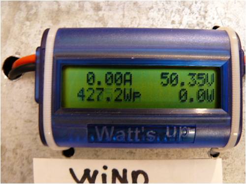
Jim |
||||
| KarlJ Guru Joined: 19/05/2008 Location: AustraliaPosts: 1178 |
Those caps look real small I believe 450V rated caps were the go these would be 1.5" round by 2" tall. Per the cap mod page, dont you need a no cap link too for the top end, they would take some of the load off the caps? All the feedback you get on this im interested in! Luck favours the well prepared |
||||
| GWatPE Senior Member Joined: 01/09/2006 Location: AustraliaPosts: 2127 |
Hi Jim, The capacitor voltage multipliers are only expected to pass approx a maximumm 20% of the windmill maximum power. They work in addition to the normal rectifiers. The caps in the photo are ????. The 400V electros I use are much bigger [physically]. I am currently working on a high [200V] voltage system using a cap voltage doubler, and cap voltage tripler. These are in addition to the normal rectifiers. BTW my mill begin furling at around 30kph, Going for higher wind furling can result in failure of a windmill component during gusty conditions. Gordon. become more energy aware |
||||
| KarlJ Guru Joined: 19/05/2008 Location: AustraliaPosts: 1178 |
Gordon I read all your posts on the voltage doubler. I make it 680uf 450V in series back to back (x12) of for the three phases for a single 48V f&p. I also noticed you managed to source all your bits for "less than a dollar each" ....where! best I can do is $61 USD for 24 pieces of "nippon chemi tube amp caps" from supplier below out of the USA. http://cgi.ebay.com/ws/eBayISAPI.dll?ViewItem&item=270476268 292&ssPageName=ADME:X:eRTM:US:1123 Hope this doesnt class as a thread hijack! Karl Luck favours the well prepared |
||||
| JimBo911 Senior Member Joined: 26/03/2009 Location: United StatesPosts: 262 |
Gordon The caps are bi polar audio 50uF100v. I wired the mill through the caps ONLY, so I should include both the caps/doubler and an separate rectifier simultaneously? I will keep a watch as far as furling cut in kph. No I have not had a storm or strong winds so I will not change furling at this time. Karl I have got a lot more to learn. I did print the pages on caps mods but haven't kept up on my reading. As winter approaches I will have more time to dig deeper. Thanks for your responses. Jim |
||||
| JimBo911 Senior Member Joined: 26/03/2009 Location: United StatesPosts: 262 |
Gordon Been reading your pages on cap mods. Guess I should have read them earler. I now have a much better understanding of the voltage doubler and how to correctly wire them to my mill. Looking forward to improved output. Thanks. Jim |
||||
| KarlJ Guru Joined: 19/05/2008 Location: AustraliaPosts: 1178 |
JimBo I just put together a similar set of blades, did you use some exhaust tube up the guts of 80% of the blade, caus I cant see any rivets out there, most of the blades I've seen on this forum have the 3odd rivets each side fairly evenly spaced and further out than their piece of solid bar. Fillm has even had them move outwards on the rivet, squashing the plastic in the process, perhaps a couple of 1/4 rivets out toward the ends of the blades for good measure. Luck favours the well prepared |
||||
| JimBo911 Senior Member Joined: 26/03/2009 Location: United StatesPosts: 262 |
Karl I did not care for the plug welding used by some members I don't feel comfortable with the idea of welding to a thin tube heat stress can cause a harding of the area around the weld leading to cracking etc. I used three 1/4 20 stainless bolts with nylon locking nuts and washers to fasten the blade to the iron cores then pop riveted the remaining blade to the tube accordingly. OK here's the BIG difference from mine and some of the other form members I used aluminum tubing instead of steel. The aluminum being much lighter then steel to help keep rotational stress to a minimum. I know I will probably here it from some forum members (aluminum blades) but so far they seem to work just fine. I also think the the lighter blades help track the wind direction and respond to different wind speeds quicker. The idea being that lighter is more forgiving on rotating forces. 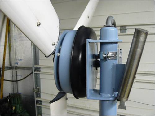
Jim |
||||
| JimBo911 Senior Member Joined: 26/03/2009 Location: United StatesPosts: 262 |
Gordon I finally wired my voltage doubler in parallel (not series) with my original rectifier and I am very happy to announce the my mill DOSE make more wattage at ANY given rpm. It's a fine thing it is and it's all good. Jim |
||||
| GWatPE Senior Member Joined: 01/09/2006 Location: AustraliaPosts: 2127 |
Hi Jim, That sounds right now. The amount of power the caps provide is not a simple calc, as you will now, no doubt see. At low rpm, the mill will now produce power when normally it wouldn't. At higher rpm, the proportion diminishes. At low rpm the proportion is 100%, and this reduces down to approx 10% at full output. The amount of time the mill spends at any power level will determine the relative gain, but the loading will be more optimum to the wind energy. Well done. Gordon. become more energy aware |
||||
| fillm Guru Joined: 10/02/2007 Location: AustraliaPosts: 730 |
Jim , You have done a neat job with this mill but the idea of the light aluminium tube makes me cringe as aluminium has no strengh and fatigue qualities . I hope the mill is not close to other houses and people when you are in for a big wind day . I am just surmising here ,but did you go for thicker walled Al tube and then have to machine down the steel solid ? I to did not like the idea of plug welding , but think it is the best simple high strength option as drilling holes through the solid also weakens it considerably at that point , if the plug welds are kept back 50mm or so from the load point there should be no affect in that area . In saying that in my latest hub design I have put 1 hole through where I believe to be a non criticial area through the solid and s/s tube , but the solid is now 4140 high tensile and is 3 times longer than the blade spigot that failed at the load point due to an incorrectly placed plug weld . I am not concerned about the weight factor . There are forces on a wind turbine blade that are trying to ripp it of its mount from every direction and to compromise strength for weight in this area is asking for disaster , if strength is lightness is needed , it costs , chromoly 4130 tube PhillM ...Oz Wind Engineering..Wind Turbine Kits 500W - 5000W ~ F&P Dual Kits ~ GOE222Blades- Voltage Control Parts ------- Tower kits |
||||
MacGyver Guru Joined: 12/05/2009 Location: United StatesPosts: 1329 |
This may be true for all metals and not just aluminum, but I've personally watched as solid aluminum is stretched to its breaking point on a machine that measures its static tensile strength at the point of parting. As the metal approaches the breaking point, its tensile strength increases and is several times stronger just before it parts than it is in a relaxed state. You may want to do a little ciphering (math) and figure out the angular acceleration on the blade roots at various speeds before mounting this thing anywhere near "civilization". I had a blade let loose once in gale-force winds (70+mph) when there was no load on the turbine and I was out saving someone's life (US Coast Guard). My neighbor said the last he saw, it was headed for the Gulf of Mexico, about 1/4-mile away! The other two blades "extruded" themselves around my tower. My blades were hollow, high-aspect-ratio, aluminum and were mounted to a solid aluminum root with steel screws as well as aircraft-quality pop rivets (called kleekos). My point in telling you all this is -- it can get pretty dangerous, so be careful. Nothing difficult is ever easy! Perhaps better stated in the words of Morgan Freeman, "Where there is no struggle, there is no progress!" Copeville, Texas |
||||
| KarlJ Guru Joined: 19/05/2008 Location: AustraliaPosts: 1178 |
Clecos are pins that are used with a special pair of pliers they have three pins one in the center and one either side . As you pull them with the pliers the two pins on the side move out and together and barbs grab when you release the pliers as the two on the side are expanded by the pin in the middle. They are used to hold joints together temporarily only. Aircraft pop rivets are to name a few. cherry, cherry max, cherry locks, Jo bolts, ergotech's. jo bolts are currently used extensively and use a nut and bolt, gun screws the centre outwards forming the tail, then snapping off, pins must be then ground flush. They are normally titanium and very sensitive to grip lenght sold in 0.050" increments and start at a couple of dollars each and go into the hundreds of dollars each for O/S. in our uses stainless is as good if not better and you can buy them at the hardware store. Luck favours the well prepared |
||||
| The Back Shed's forum code is written, and hosted, in Australia. | © JAQ Software 2026 |
