
|
|
Forum Index : Windmills : 1.5kw 6 pole motor conversion
| Author | Message | ||||
Smart Drives Senior Member Joined: 06/07/2009 Location: AustraliaPosts: 115 |
OK i cant get the smaller version of the magnets i am using so its full steam ahead with what i have. I will expoxy on wednesday and post a photo. Cam. All smart drive parts sold Custom built turbine parts on Multicam flatbed CNC Router |
||||
| Smart Drives Senior Member Joined: 06/07/2009 Location: AustraliaPosts: 115 |
Work has been crazy , planning to expoxy this friday. Cam. All smart drive parts sold Custom built turbine parts on Multicam flatbed CNC Router |
||||
| Smart Drives Senior Member Joined: 06/07/2009 Location: AustraliaPosts: 115 |
After three weeks of 16 hour days i will finally be epoxying next week, but i got two suprises this week. (1) was the old 12v chinese turbine hit 38 amps ! in a gust and (2) my test rig with a new 60S (decogged by factory) wired in half series half parallel (star) hit 10 amps at 52v. I cant wait to see what it does running at 24v (delta) , i reckon it will hit 760 watts (31amps) Cam. All smart drive parts sold Custom built turbine parts on Multicam flatbed CNC Router |
||||
| KarlJ Guru Joined: 19/05/2008 Location: AustraliaPosts: 1178 |
good luck with that Cameron sounds great BTW do you have any graphs of 60s in 2x7c delta vs 80s in 2x7c star? I'm thinking they would be very similar but you're the man in the know when it comes to this Luck favours the well prepared |
||||
SparWeb Senior Member Joined: 17/04/2008 Location: CanadaPosts: 196 |
...We eagerly await news of your results... (No pressure man!)  Steven T. Fahey |
||||
| Smart Drives Senior Member Joined: 06/07/2009 Location: AustraliaPosts: 115 |
Hi Karlj, I actually dont have any info on that hook up, sorry. I need to know what voltage you are running and i can give you an approximate. Finally i had a chance to epoxy, now i just have to wait a week for it to cure. The guys i bought it off said i only needed it under the magnet but i have played it safe and glued the edges of the magnets aswell. 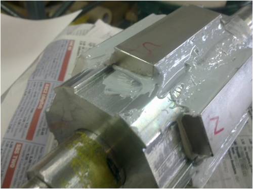
All smart drive parts sold Custom built turbine parts on Multicam flatbed CNC Router |
||||
Bryan1 Guru Joined: 22/02/2006 Location: AustraliaPosts: 2174 |
Hi Cameron, With my 1.5 kw conversion I full epoxied the magnets and rotor then machined the epoxy to size. This will ensure if any water ingress's into the motor the neo's are fully sealed and won't start to rust. Cheers Bryan |
||||
| Dinges Senior Member Joined: 04/01/2008 Location: AlbaniaPosts: 510 |
Looking at this picture, I notice that the magnets are much shorter than the stator length (if the length of the rotor is the same length as that of the stator, which I assume to be the case). If so, a 10 degree skew will not be enough. The shorter the magnets are, the more skew is needed. 360 degrees/36 slots = 10 deg skew, *assuming* the magnets cover the entire length of the stator. In your case, I expect the angle would need to be 100/75=1.33 times larger, i.e. 13.3 degrees. (if the stator has a length of 100mm, and the magnets are 75mm long) I think you will find your rotor will cog at least some. Hopefully not a lot, but will be interesting to see what the results are. Peter. |
||||
| Smart Drives Senior Member Joined: 06/07/2009 Location: AustraliaPosts: 115 |
Ahh, I was wondering why my skew didn't look as much as others i have seen. The rotor is actually 120mm long which means i should have skewed them at least 15 degrees by the sounds of it. Oh well it will be intersting to see what my startup wind speed will be. The rust issue will be handled hopefully by a couple of coats of polyurethane. Cam. All smart drive parts sold Custom built turbine parts on Multicam flatbed CNC Router |
||||
| Dinges Senior Member Joined: 04/01/2008 Location: AlbaniaPosts: 510 |
[quote]The rotor is actually 120mm long which means i should have skewed them at least 15 degrees by the sounds of it[/quote] The stator is the determining factor, not the rotor. If the stator is 100 mm long, the skew angle should be correct for that. Length of the rotor does not influence the skew angle. The length of the magnets (relative to the stator length) does influence the angle. [quote]Ahh, I was wondering why my skew didn't look as much as others i have seen.[/quote] Which angle did you make 10 degrees, beta or delta? 
Notice that beta should be 10 degrees (assuming the entire stator is covered with magnets, not just part of it, as in your case), and that, depending on the length and diameter of the rotor, delta may be smaller, larger or equal to 10 degrees. Peter. |
||||
| Smart Drives Senior Member Joined: 06/07/2009 Location: AustraliaPosts: 115 |
I am fairly sure the way he put the rotor on the slotter that delta is 10 Degrees. BUT Murphy has reared his ugly head and the rotor doesn't fit back in !  Seems you shouldn't let an engineer use a vernier caliper. I was assured it would fit even after mentioning that the points of the magnets had to fit when half rotated. So in my frustration Seems you shouldn't let an engineer use a vernier caliper. I was assured it would fit even after mentioning that the points of the magnets had to fit when half rotated. So in my frustration  out came the angle grinder and presto it should fit now. out came the angle grinder and presto it should fit now.
Its times like this i wish i had my own lathe. 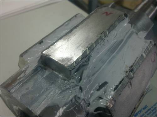
All smart drive parts sold Custom built turbine parts on Multicam flatbed CNC Router |
||||
| KarlJ Guru Joined: 19/05/2008 Location: AustraliaPosts: 1178 |
brutal but effective! cunning, I like it The 80s 2x7c vs 60s 2x7c delta was for a 24V solution as I may not be able to afford a PVE 1200 straight up and there are lots of things to do with 24V...... Cheers Karl ps sorry for the hijack Luck favours the well prepared |
||||
oztules Guru Joined: 26/07/2007 Location: AustraliaPosts: 1686 |
The engineer may have done you a favour 
Your gap will be that much smaller now.... better flux in the gap than your situation before perhaps... 1mm? ..............oztules Village idiot...or... just another hack out of his depth |
||||
| SparWeb Senior Member Joined: 17/04/2008 Location: CanadaPosts: 196 |
That happened to my last motor conversion, but before I glued them on! I was able to put the grinder to the rotor flats, not the mags. Steven T. Fahey |
||||
| Smart Drives Senior Member Joined: 06/07/2009 Location: AustraliaPosts: 115 |
ALL DONE... The motor is a bit hard to turn but a big set of blades should solve that problem.. the question is.. how big ? The gap would be 1mm or less. Hi Karl, hope i have the new code for wiring methods right. If i do this should be fairly close. Looks like you will have a very low startup speed with 80s 2x7c (200rpm or less) but i cant see your power getting over 300 watts. 60s 2x7c will startup at even lower rpms but power will be similar. Best setup would be 80S 24v star , wired in half series half parallel startup is 250rpm - 400 watts at 420rpm max output 600 watts at 900rpm. (as above in delta puts out 900watts but startup is 450rpm) 60S 24v delta, wired in half series half parallel startup is 280rpm - 400 watts at 500rpm , 600 watts at 750rpm. Hope this helps. I will post a photo of the finished product with blades next week. Cam All smart drive parts sold Custom built turbine parts on Multicam flatbed CNC Router |
||||
| HeadsUp Regular Member Joined: 06/12/2009 Location: AustraliaPosts: 43 |
curious why you guys didnt identify your magnet configuration ? there are many options , including halbach arrays to improve EMF and decrease losses also , this article is worth reading to see the efficiencies derived from North/north torus motors and different coil constructions and layouts torus Axial Flux motors 
mini halbach arrays could be used here by using small magnets on each end with opposing poles facing towards the main magnet to reflect the magnetic field back towards the center of the stator |
||||
| Smart Drives Senior Member Joined: 06/07/2009 Location: AustraliaPosts: 115 |
Hi Headsup, I used single magnets so it was just N,S,N,S,N,S. I would have liked to stick extra magnets on the ends but they didn't come in the size i needed. Cam. I have just returned from the annual family gathering and to my suprise the wind meter has a max wind speed of 148km/h on it ! i cant believe my new mill hasn't been damaged...Especially the thrust bearing Yaesu GS-050 (they just dont seem that strong) All smart drive parts sold Custom built turbine parts on Multicam flatbed CNC Router |
||||
| Dinges Senior Member Joined: 04/01/2008 Location: AlbaniaPosts: 510 |
I'll respond as it is my rotor/pictures you are referring to. [quote=Headsup]curious why you guys didnt identify your magnet configuration ?[/quote] Because it seemed so obvious to me as to not warrant mentioning. Your upper picture describes the correct situation (N-N-N magnets on each row, next row S-S-S, etc.) [quote]there are many options , including halbach arrays to improve EMF and decrease losses[/quote] True - there are many ways to complicate this project. But the law of diminishing returns applies. It takes a lot of cost and effort to increase output just a little bit more using an Halbach array . If I wanted more power, I'd have taken a larger motor (10kW instead of 7.5kW) and add another ring of magnets. Easy and cheap. Wrestling the magnets in place was hard enough as it was, let alone if the extra Halbach magnets had to be put in place as well. You suggest Halbach arrays; I'm curious whether you know what those custom magnets (small volumes of odd-shaped magnets) would cost? Do you have figures for that? The only real effect of Halbach arrays would be that you would have a slightly smaller generator (more power per kg or m^3 of generator). As this generator isn't supposed to end up on an aircraft or launched into space, a few extra kg of weight don't matter. Frankly, hearing of this Halbach 'solution' on internet fora gets tiresome. It's a solution to a non-existant problem. It's a complicated solution to implement in practice. It's an expensive solution, when the alternative is simply taking a 33% larger motor and slapping on 33% more magnets (12 pcs. of 5E, so 60 euro for an extra kilowatt or so). How much would it cost in custom Halbach magnets, and how much extra power would it yield? I strongly doubt it'd be a kilowatt.... Peter. |
||||
| Smart Drives Senior Member Joined: 06/07/2009 Location: AustraliaPosts: 115 |
With a few modifications this will be the thrust bearing for motor. Wheel bearing of a car. 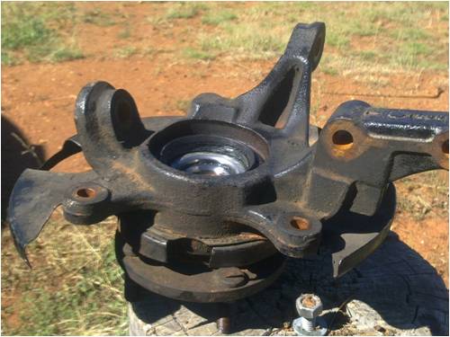
All smart drive parts sold Custom built turbine parts on Multicam flatbed CNC Router |
||||
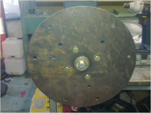
| Smart Drives Senior Member Joined: 06/07/2009 Location: AustraliaPosts: 115 |
I have finished the flange that will allow me to now attach the blades. I did a test spin by hand and the motor easily reached 30-40 volts (approx 180rpm), so i think i will hook it up as a 48v system to start with and see what i can get out of it. The cogging i would guess is similar to a smart drive motor that hasn't been filed. BETTER than i was expecting. 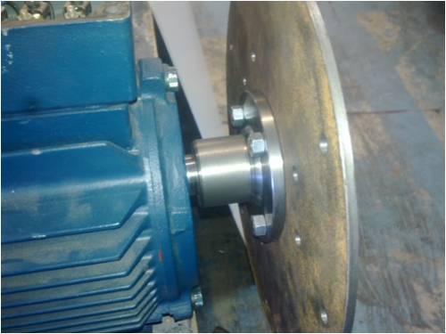
All smart drive parts sold Custom built turbine parts on Multicam flatbed CNC Router |
||||
| The Back Shed's forum code is written, and hosted, in Australia. | © JAQ Software 2026 |
