
|
|
Forum Index : Windmills : I finally got an F&P where to now?
| Author | Message | ||||
KarlJ Guru Joined: 19/05/2008 Location: AustraliaPosts: 1178 |
I like the suggestions but i'll need to un rivet the blades from the shaft first. I'm thinking I'll lighten the heavy blade for starters, cut off an inch or so of the steel tube, I have plenty of meat to spare there, my steel tubes are only 100mm short of the blade end and Anthony tells me upto 200mm short is OK. It just takes copious quantities of time.... I'll buy some scales as Phill suggested should save me assembling and disassembling at least a couple of times. the hub is a bit tedious to work with as everything has to go together evenly.. Luck favours the well prepared |
||||
Downwind Guru Joined: 09/09/2009 Location: AustraliaPosts: 2333 |
This balance thing has got me thinking. This method is to late for yourself Karl but might be of interest to others. Firstly would be to check the balance of the hub and spiders without the blades fitted and adjust the spider length to balance. Secondly would be not to glue the end caps in. Assemble the blades with end caps inserted. Check balance and if needed add cut strips of lead sheeting or solder and sticky tape it to ends of blades, until balance was gained. Remove the end caps and stick the lead weights inside with silicon. You can cut up the lead to suit and fit within. Glue end cap in place and blades should be balanced. The force applied to the rotating blade will hold the lead in the end and only need enough silicon to hold it in place when blades are stopped. Pete. Sometimes it just works |
||||
fillm Guru Joined: 10/02/2007 Location: AustraliaPosts: 730 |
If you get everything in balance as you assemble and prior to riveting , then the final perfect balance can be done with silastic on its own in the end caps . Adding to much weight to the caps is not a good idea . It is also good to glue a correct size small washer on the inside of the cap to allow the rivet to bite on. When removing the rivets with a drill you will have to keep the drilling cool with water or it will melt the hole ( Battery or Air Drill ) Balancing the blades is important but equally important is " Tip Runout " , if the tips do not track within 0 to 5mm you will get vibration at centain rpms. PhillM ...Oz Wind Engineering..Wind Turbine Kits 500W - 5000W ~ F&P Dual Kits ~ GOE222Blades- Voltage Control Parts ------- Tower kits |
||||
| KarlJ Guru Joined: 19/05/2008 Location: AustraliaPosts: 1178 |
sounds like you've been down this road a few times Phill. Pete I agree, after all the work thats required to assemble the blades, plug welding etc etc etc, gluing in the end caps is easy, and if you could add a few 10c pieces in the cap before final assembly would make it that much easier. I dont know what they are glued in with but the caps certainly dont come off easily, I gave up quickly on that idea for fear of damaging blade or cap. Luck favours the well prepared |
||||
| Downwind Guru Joined: 09/09/2009 Location: AustraliaPosts: 2333 |
I didnt realize the end caps were glued in when you get them. Being pvc then the blue glue plumbers use would work fine i would think, as long as you prime the pvc first. Maybe Phil coulds supply them with the end cap loose if requested to allow for easy balancing. My point being 10 cents at the end of the blade may be equal to $10.00 added to the hub. Than i would expect phil has already crossed may of these bridges and know more than me guessing. Pete. Sometimes it just works |
||||
| KarlJ Guru Joined: 19/05/2008 Location: AustraliaPosts: 1178 |
Blade balancing tomorrow. had kids today but got these almost finished. House end dump load and voltage controller 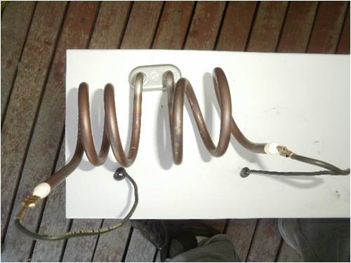
and 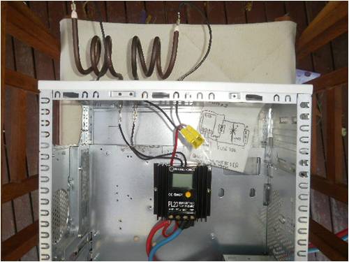
and about the 5th iteration of the volatge doubler 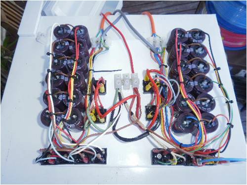
Luck favours the well prepared |
||||
| fillm Guru Joined: 10/02/2007 Location: AustraliaPosts: 730 |
Karl , Make sure the diode that is supplied with the pl20 is used accross the output to the dump load and orientated correctly or you will be up for another pl20. Looks like its almost ready . PhillM ...Oz Wind Engineering..Wind Turbine Kits 500W - 5000W ~ F&P Dual Kits ~ GOE222Blades- Voltage Control Parts ------- Tower kits |
||||
| GWatPE Senior Member Joined: 01/09/2006 Location: AustraliaPosts: 2127 |
Hi Karl, I try and keep the wire interconnect lengths as short as possible. Here is a link to some pics of my arrangements. doubler and trippler looks good though all loomed up. Gordon. become more energy aware |
||||
| KarlJ Guru Joined: 19/05/2008 Location: AustraliaPosts: 1178 |
Phill diode is there, I wrapped 80% of the conductors in heat shrink so it couldnt touch anything else in between and the two ends go into the terminals behind the wiring you see. Gordon I figured as they are carrying minimal current it wouldn't be that critical. If its 20%max then we're talking 120W split over the three phases, split over the two sets of caps, so I assumed they'd carry 20W or so each, even if its 60W each @48V or better we're still talking very little current. If its that critical perhaps I should solder all my links instead of having connectors..... Karl Luck favours the well prepared |
||||
| GWatPE Senior Member Joined: 01/09/2006 Location: AustraliaPosts: 2127 |
Hi Karl, I have posted DSO pics of output waveforms. There are high speed switching spikes associated with these arrangements. All wiring is a potential antennae and you should keep all interconnects as short as possible. There is enough RFI out there, without unnecessarily making more. The power handling is not really a player here. Gordon. become more energy aware |
||||
| KarlJ Guru Joined: 19/05/2008 Location: AustraliaPosts: 1178 |
Ahh Gordon, what would I do without you. The inputs were originally elsewhere and I didnt think I'd bother here is the excess wire cut out 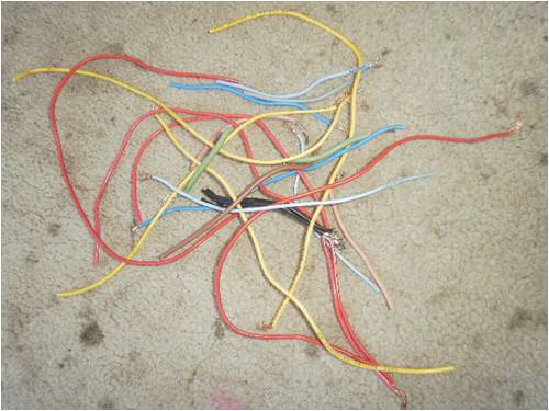
here is iteration 7 (and the last- remaining wire is tough) 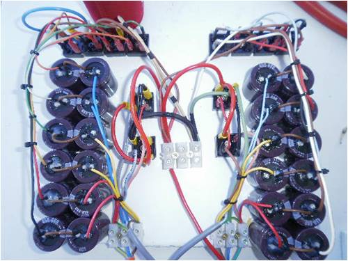
Last ....wait for it....the faraday cage! (also known as a fridge) Revolutionary in wind turbines I reckon. 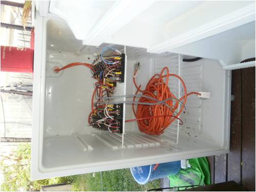
wire bundle at the bottom is the wire that will run up the tower. Luck favours the well prepared |
||||
| GWatPE Senior Member Joined: 01/09/2006 Location: AustraliaPosts: 2127 |
Hi Karl, old fridges are good for all sorts of purposes. I use one to store kindling. Is a normal 500L cabinet though. I was a bit short with space in my metal enclosure, as I have many more caps. I tend to use enamelled winding wire, for the fixed interconnects. I use flex for the external connections only now. I have my trusty SS long nose pliers that are perfect for removing the enamel prior to soldering. Wire that I would have just recycled makes good short interconnects. You seem to have things well sussed now. Gordon. become more energy aware |
||||
| KarlJ Guru Joined: 19/05/2008 Location: AustraliaPosts: 1178 |
now need to concentrate on getting the tower up.... working bee anyone? Have to take down next door neighbors windmill, was a southern cross, fairly small tower three legs about 1m apart at the base work out how to add on up at the top a hinge mechanism. needs to be a self supported rig. This was my idea Karl 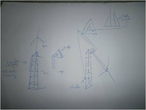
most of the construction is incredibly light, i'll probably replace the wire cross pieces with angle steel. Luck favours the well prepared |
||||
| JimBo911 Senior Member Joined: 26/03/2009 Location: United StatesPosts: 262 |
Karl Nice work on the caps!!! Now make another and mail it to me !!!!!!! ASAP  Jim |
||||
| KarlJ Guru Joined: 19/05/2008 Location: AustraliaPosts: 1178 |
Jimbo can do without any drama but postage is the killer. for 12 caps is about $30 USD but $30USD to get them to me + the rectifiers 6 for a complete rig (ie two to handle main output too) at $5.50 each. so thats $90 USD plus postage to you. I would have thought now you have bulk expertise (your mill puts mine to shame) you would have no dramas yourself and it would save all those round the world postage trips. Phill advised that the 680uF 450V caps were the best for our 80 series in 2x7c wiring rather than the 7x2c you have now for 12V. Obviously works for this setup at 48V+ Trick is one step at a time. print out the schematic and label your rectifiers 1-4, start soldering and or crimping until all the connections are done. split your caps into phases ie 4 for each phases and wire one phase at a time. when there are no connections left to do you're finished. I mounted on a piece of steel cut from the side of an old microwave as its powdercoated and works as a heat sink too (not that I think they will generate much heat as everything is sized too big). I think we all wish our 35A rectifiers werent big enough! 35A x2 for main power handling (again not sure if it quite works out this simple but) 70A at say 55V = 3850W. given mine will probably only see 4-600W max they should barely even see a temp rise. I would like to see a circuit for the triplers so I can build that too and perhaps buy enough bits to make 4 doubler/tripler arrangements to economise on the components (postage and such) and then sell at component cost +say $40 to keep the missus off my back. That way I could sell them to forum members and would work out cheaper than them buying just the bits to build themselves. also I guess doubler/tripler starting to look pretty busy and may be a little much for some. Problem with this theory (making a few) is that this combo of caps works best on an 80s in 2x7c so what for the other combos, will probably work well enough but Gordon's baby he would know. Karl Luck favours the well prepared |
||||
| JimBo911 Senior Member Joined: 26/03/2009 Location: United StatesPosts: 262 |
Karl Hey thanks for the return but that's Ok you have been working hard on your mill etc. Just commenting on your work with a little humor. Keep up the good work. For me it's been one step at a time with lots of help from all the forum members. Today we had 20 to 30 mph winds for the first time and she's still flyen, have to make a change on the tail. Thanks again Jim |
||||
| KarlJ Guru Joined: 19/05/2008 Location: AustraliaPosts: 1178 |
furling late or early?? Phill reckons 500-600 rpm should be tops as you forces are getting pretty big by then... Luck favours the well prepared |
||||
| KarlJ Guru Joined: 19/05/2008 Location: AustraliaPosts: 1178 |
Back to blade balancing.... not having much luck, getting close but not perfect. bought some digital scales but even if all the blades are identical they wont necessarily be balanced right? as the centre of gravity of each blade may be different. my blades are about 30g apart now that I've cut one of the pieces of tube down 3" and another 1". Now i'm stuck with making the light blade heavier. incidentally they weigh 4100-4130g each...this surprised me Karl Luck favours the well prepared |
||||
| fillm Guru Joined: 10/02/2007 Location: AustraliaPosts: 730 |
Karl , Make sure that the tip to tip measurement is with in a couple of mm . Are you still trying to balance them horizonitaly , I find that vertical on a test stand is best , but you have to have a still place to do this . 4.1Kg , thats why the mounting system needs to be strong , when you see those spinning at 500+Rpm and yawing and furling its a eye opener to say the least PhillM ...Oz Wind Engineering..Wind Turbine Kits 500W - 5000W ~ F&P Dual Kits ~ GOE222Blades- Voltage Control Parts ------- Tower kits |
||||
| KarlJ Guru Joined: 19/05/2008 Location: AustraliaPosts: 1178 |
indeed just spinning it up in the yard with a cordless drill, no rotor attached to stator, drill was smokin and maxed out I guess at perhaps 70rpm, Yaw bearing has some play in it so even with 30g difference in blade weight she was jumping around a bit. Back to Aircraft as a quality inspector....got me to thinking. An extra couple of coats of paint on the light blades and one washer at the root of one blade whala.... blades are now identical weights. normal spray tin holds 300 odd grams of paint, half of this is solvent which will evaporate giving you 150g of weight to add and it sprays on! (i did use a special plastic primer)I figure if it erodes on the blades it will erode evenly across all three. keeping the balance over time. all now 4130g. now back to the string idea horizontally, i think there's too much drag on the bearings to do it on the mill and i cant imagine the tilt back of the blades helps either. have to wait until the paint dries now.... Luck favours the well prepared |
||||
| The Back Shed's forum code is written, and hosted, in Australia. | © JAQ Software 2026 |
