
|
|
Forum Index : Windmills : - NEW ALUMINIUM BLADES -
| Author | Message | ||||
Greenbelt Guru Joined: 11/01/2009 Location: United StatesPosts: 566 |
FILM SAYS: bit annoyed when all the advise on how and what to do and why , when no one has actually worked out what loads we are dealing with , how much centrifical force is exerted by a 4kg blade @ 1000 rpm and can they reach 1000rpm ,so why not set that as the bench mark , I've seen 780. How much axial forces are we dealing with in the gyroscopic forces wind forces furling/yawing forces at 75% in from the blade tip as well as at the root . Can it be worked out here on the forum in a constructive manner ? How to figure the centrifugal force on your turbine Using the Formula below I will try to give some understanding to the use of it. An Example of a real blade you plan to use. ( w ) is two times the value of the constant PI. (2*times 3.1416 = 6.2832 This is multiplied by Your desired maximum (RPM) and Divided by 60 to get the radians swept each (second). this result is multiplied by itself, (squared).Then multiply this squared number by ( r ) the radius of your mill blades. distance from the mill Hub to the blade tip,(in Meters).All the above is the value of (w) And finally multiply, (W) by (M) the weight of your Blade in kilograms. ( r ) is distance from hub to tip- (your own Blade measure in meters ( m ) is the weight of the blade in kilograms.(Mass Example numbers plugged in. (W) = 2 X 3.1416 = 6.2832 x 500 rpm.= 3140/60 seconds = (squared) 52.33 x 52.33 = 2738.7 x (r) 1.2m = 3286.5 x (m) 3.5 kg = 11502.86 total force in newtons. = 2,589 pounds This is shorthand English. W=6.28 times RPM divided by 60 seconds then squared then multiplied by (R)radius, then multiplied again by the mass(M) FILM suggested a design max. of 1000 rpm. to handle the storm loads, Here is what that looks like, W=6.28 x 1000=6280/60sec=104.66X104.66=10955.11 X (r) 1.2 = 13146.13 x (M)3.5 = 46011.46 newtons. Divide newtons by 4.44822 to convert to pounds------10,344 pounds= 5.15 US TONS plus gyro forces and vibration. Next time you take your Cessna out for a joy ride, Show a little sympathy for the Prop. (R)= .8m. (M)= 4.1kg HARDWOOD rpm 2450 loaded.(GUESS) IN case you haven't discovered that I don't know a D.Thing about Math. I confess, it has taken all day and most of the evening trying to make sense out of this expression so that I could present it in way that people would not be turned off by a bunch of symbols. Until today I had no Idea how to calculate centrifugal force, There have been times I wanted to but no urgent need came along to force it on me. Maybe this will help some people, who like my self do not have a good handle on science math. If anyone finds errors that are serious here, please post a correction, I want it Right.---Roe 1 kilogram is equal to 9.8066 newton's or 2.20465 pounds 1 pound force = 4.44822162 newtons Time has proven that I am blind to the Obvious, some of the above may be True? |
||||
fillm Guru Joined: 10/02/2007 Location: AustraliaPosts: 730 |
Good point Pete , I have thought about noise resinance from the blades as well , but don't know the answer to that untill they go up . As with the s/s tube , I started with that as my choice , it is easy to get , and doesn't have rust problems . It might look good but you dont see it in this application . And I will be corrected if I am wrong , it has a higher mechanicial strength than normal steel tube of the same wall thickness . I fully agree " design it out " but to design anything out , you need to know what you are designing it to stand up to . PhillM ...Oz Wind Engineering..Wind Turbine Kits 500W - 5000W ~ F&P Dual Kits ~ GOE222Blades- Voltage Control Parts ------- Tower kits |
||||
| fillm Guru Joined: 10/02/2007 Location: AustraliaPosts: 730 |
Thanks Greenbelt for the time and effort spent in working that out , also for the time it would have taken to put it all into a post .  PhillM ...Oz Wind Engineering..Wind Turbine Kits 500W - 5000W ~ F&P Dual Kits ~ GOE222Blades- Voltage Control Parts ------- Tower kits |
||||
| dsmith1427 Newbie Joined: 21/07/2009 Location: United StatesPosts: 5 |
What some call negatives, I call critical analysis. As an automotive engineer we do it all the time. It is a requirement! All systems, subsystems, and components go through a Design and Process Failure Mode Effects and Analysis (DFMEA & PFMEA). These processes ask the questions what is the function of the design and what if some aspect of the function is missed. For the aluminum blade some of the design functions may be as follows: Extract energy from the wind operate quietly Be aesthetically pleasing Be easy for a customer to assemble For each function, the product development team will brain storm possible failures in the design and design out the failures as best as possible. There are ALWAYS trade offs. Process FMEAs deal with what can go wrong in the manufacturing of the blades. The outcome of the P-FMEA is to creagte a process where product failure is not a function of manufacturing. I see this forum is a great sounding board for this type of activity. That being said, there is no such thing as an easy design. When safety is involved, analysis should be very critical. It does not matter if you are selling to one person or a million people, you are responsible for your design. It better be safe! In my opinion, your design is complex. A wooden blade is made from a homogeneous material. It may have two components - wood and an adhesive - that have withstood many environmental tests. The aluminium blade design has many components of different materials and the function of each component for this application should be evaluated. One evaluation may be as follows. Is 1000 RPMs the maximum rating for the blades? If the ultimate force due to the 1000 RPMs is 40kN, the rivets will have to carry this load as well as the other loads in the assembly. How many rivets does the assembly require? What happens when one rivet fails? Will this failure lead to failure of the other rivets? How should the rivets be spaced? What is too close? What is too far apart? Aluminium alloys corrode. Does galvanic corrosion occur between the Alunimium rivets and steel rod? Does it occure between the steel rod and the Aluminium extrusion? Is the extrusion made from Clad aluminium to resist corrosion from the environment? If the answers are critical to the function of the blade, they will have to be answered with a design solution. There are many factors in this design and if you are going to sell it to the public, you owe it to your customers and the community where your customers live to provide a safe and reliable design/product. I would encourage you to continue with your product design but I would caution you to think twice when some says "it's easy" or design one factor out of the equation. Call me crazy but I like having my ideas criticized. I actually think this process is fun. Anyway, it is how I learn and to do this process on a global scale through this and other forums provides a great learning tool... enough said! Go have fun. Don |
||||
Downwind Guru Joined: 09/09/2009 Location: AustraliaPosts: 2333 |
Fillm, I would think SS may have a higher rate of fatigue than steel. I have no hard data on this but if you place a SS rod in the vice and bend back and forth it will snap faster than steel. The initial strength might be greater but i question the over time factor verses fatigue. SS is easy to weld but needs one to have SS rods to weld to steel and this can add a huge cost to the home builder if they need to buy a pack of SS elctrodes for a half dozen plug welds. ( also the fatigue around the weld) I fully understand how hard it is to view all design points of views and design them out and only time and feed back can achive this but the negitives posted here are of great value towards creating a better product its just a pitty more surgestions on solving the problems are not given.( good or bad ) It is important not to loose sight of the fact that most constructors are what might be discribed as Bush Mechanics, and not to over engineer a design that cannot be coppied easily for the average constructor. But in doing so also retain integrity. Just read the posting by Don and could not agree more. Negatives are a way forward to being positive with a result. It is nice to see some people getting off their ass and not sitting on the fence with what will be a great product if used correctly. Pete. Sometimes it just works |
||||
| frepdx Newbie Joined: 16/11/2009 Location: Posts: 7 |
I'll second that notion. Phill, just a thought on corrosion ... many finished aluminum parts are treated to inhibit corrosion, the manufacturer of the extrusion might be able to do this. You never know, they might already have. The standard treatment used to be a chromate conversion coating, sometimes called chemical film or Chem-Film. It can be clear but is often yellow (you've all seen those small stamped steel parts that are zinc plated but yellow - that's often a chromate conversion coating on top). Chromate coatings are being replaced by more environmentally friendly treatments nowadays I hear, but they serve the same purpose. This treatment not only reduces corrosion but primes the aluminum so it takes paint and adhesives. So you might want to inquire about it. |
||||
oztules Guru Joined: 26/07/2007 Location: AustraliaPosts: 1686 |
Greenbelt, Would it be true that the workings you have used, actually only demonstrate the force of your final mass at maximum radius.... ie it is really saying that you get 5 tons for a weight of 3.5 kilos at 1.2 meter radius? This is skewed to all the mass of the blade being at the outer tip..... which is patently untrue. Center of mass will be at .6M or thereabouts..... what do we do now? Ok, the centrifugal force is interesting for composite rivet/tube/solid/blade only calculations, as they may pull apart....but is easy to bench test and fix. However, the gyroscopic forces are the ones to watch. It is these forces that will fatigue the aluminium and any other stress points which are created by composite builds. (not solid all the way) These forces are of a similar magnitude as the thrust forces (distributed across the blade length), but oscillate rapidly..(code for fatigue) It is these forces that need to be addressed with Al and stress points in mind. For a bigger set, these forces can get up to 80kg or more, but they oscillate. This means that any possible fatigue areas will not go unnoticed.... including any unsupported aluminum at the tip area.... which has to transmit these rapid oscillations to your shorter stiffer spine if you chose not to support it fully..... and any transition points (dissimilar material interface) which may be exposed to these destructive forces. I think it is these forces and their effects on the different interfaces that make it tougher to model. Extra weight in the blade set only helps to pacify the yaw.... assuming centrifugal forces are under control from the mounting... The same turning moment working on a larger mass.... slower response time.... more passive mill. .........oztules Village idiot...or... just another hack out of his depth |
||||
KarlJ Guru Joined: 19/05/2008 Location: AustraliaPosts: 1178 |
geez I'm glad someone is reading what I've written before. Stainless is crap for fatigue loads -its for piping milk. Ive seen pushbikes made of stainless fail! having an abrubt change of loading will cause anything to fail eventually. Easy to drill a hole down the guts, start with 3/16" go as far into the blade as the drill will allow. next bore a 1/4 hole to ~1" less depth, next 5/16 hole to ~2" less than the first, next 3/8" to ~3" and so on until you have a 1/2" hole about an 1" deep at the outmost end. This will smooth the transition of loading. Plain old mild steel is the best material in this application. (in my opinion) EG try breaking a 1" steel rod in tension with 6T -dreamin! there is ALWAYS a trade off, harder stiffer lighter =more brittle, less resistant to fatigue, more prone to cracking etc etc etc. Quote FILM suggested a design max. of 1000 rpm. to handle the storm loads, Here is what that looks like, W=6.28 x 1000=6280/60sec=104.66X104.66=10955.11 X (r) 1.2 = 13146.13 x (M)3.5 = 46011.46 newtons. Divide newtons by 4.44822 to convert to pounds------10,344 pounds= 5.15 US TONS plus gyro forces and vibration. EXCEPT the blade weight would probably be closer to 4.5KG (my 1200mm blades weigh 4130g each in PVC with 100mm "extra" inner steel round bar. This makes 59157N =13299pounds= 6.045T Now this has me worried. my blades are held in with a single 1/4" unbrako which obviously provides some clamp load through the hub too but would it shear off??? Luck favours the well prepared |
||||
| Gizmo Admin Group Joined: 05/06/2004 Location: AustraliaPosts: 5187 |
Are we using the correct way to calculate centrifugal force in a turbine? As Oz pointed out, it depends on where the heavy bit of the blade is. If all the weight was on the outside diameter, then the forumlar used by greenbelt would be correct, but the blade weight is spread over the length of the blade. So the "bit" of weight near the center of the turbine would exert much less force than the bit of weight at the outer diameter. Sorry Greenbelt, but I think we need to use another forumlar, or maybe break it down into stations from center to outer, and add the individual station weights to get the total weight. If we use stations 100mm long, and the weight of a 100mm length of blade at that station ( when we get past the inner rod the weight would be much less for the outer stations ), work out a centrifugal weight for that station, then add them all up. Does that sound right? Glenn The best time to plant a tree was twenty years ago, the second best time is right now. JAQ |
||||
| KarlJ Guru Joined: 19/05/2008 Location: AustraliaPosts: 1178 |
yep sounds good to me C of G of mine was about 1/4 of the entire length so obviously 1/2 the weight in the first 1/4 of the blade. formula basically assumes a 4kg weight on a string being flung outwards which is really not the case. to simplify you could cheat a little and work out speed at 1/3 of blade length with 1/2 the weight and at 2/3 with the other 1/2 the weight. this would still be super conservative. Luck favours the well prepared |
||||
| Greenbelt Guru Joined: 11/01/2009 Location: United StatesPosts: 566 |
|
||||
| Greenbelt Guru Joined: 11/01/2009 Location: United StatesPosts: 566 |
Your Right OZ; ('  ') ')
The Center of mass for an object rotating about a point which is not located within the Object. (orbiting) But ajacent to it. The problem becomes a series of calculations for centrifugal force using radius values from 0.0 to maximum in equal steps. Then find the point on the radius where the Hub end series of Values equal the Tip end results, This should give a reasonable value for the (apearant center of mass), Of course the shape of the object being studied will have a great effect on the physical location. Some mill blades have Beefy Hub sections but taper toward the tip while other's are a blunt affair with a uniform cross section. Out of curiousity I will stick my neck out and do a 7 step operation on a 700 rpm, 1.5 m radius, 4 kg.mass. Keeping it simple, the cross section is assumed to be uniform thruout its length, and its true mass is distributed equally. No stiffener bars or tubes are considered. I am using the same mass for each 8.5 inch (22 cm.) section, only the radius value changes, It seems to have a linear progression averaging 148 pounds increase from one step to the next. Different blade speed would change the number Oz is correct about the location of the (apparent center) of mass as far as I can tell from the numbers. It is located near the one meter mark 39 inches from the Hub, 66% of blade length and is within section 5 (1) w= 6.28 X 700=4396/60 =73.27 X 73.27=5368.00 X r .2143 = 1150.36 X m .57143 = 657.35 newtons/4.44809 = 147 pounds; (2) w= 6.28 X 700=4396/60 =73.27 X 73.27=5368.00 X r .4286 = 2300.72 X m .57143 = 1314.7/4.44809 = 295.56 Pounds (3) w= 6.28 X 700=4396/60 =73.27 X 73.27=5368.00 X r .6429 = 3451.08 X m .57143 = 1972.05/4.44809 = 443.44 pounds. (4) w= 6.28 X 700=4396/60 =73.27 X 73.27=5368.00 X r .8572 = 4601.44 X m .57143 = 2629.40/4.44809 = 591.13 # (5) w= 6.28 X 700=4396/60 =73.27 X 73.27=5368.00 X r 1.0715 = 5751.81 X m .57143 = 3286.75/4.44809 = 738.91 # (6) w= 6.28 X 700=4396/60 =73.27 X 73.27=5368.00 X r 1.2858 = 6902.17 X m .57143 = 3944.10/4.44809 = 886.69 # (7) w= 6.28 X 700=4396/60 =73.27 X 73.27=5368.00 X r 1.5001 = 8052.53 X m ,57143 = 4601.46/4.44809 = 1034.48 # Total = 4136 pounds. ------------------------------------------------------------ --------------- ------------------------------------------------------------ --------------- w= 6.28 X 700=4396/60 =73.27 X 73.27=5368.00 X r 1,5 = 8052 x m 4.0 = 32208/4.44809 = 7240 pounds. (This result assumes all mass is at the Tip)and is not useful, If this were a 3 meter blade then this would be a section value at 1.5 m. radius 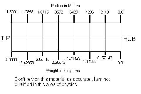
Time has proven that I am blind to the Obvious, some of the above may be True? |
||||
MacGyver Guru Joined: 12/05/2009 Location: United StatesPosts: 1329 |
Yikes! Numbers and formulas; I feel fortunate to turn a running fit of .001 and have things not squeak! All this is sounding very "engineerish". I know, my son is a PhD Aeronautical Engineer and this is what he sounds like each time he has an opportunity to corner me. Would there be any objection to my suggesting blades be reformulated using solid-core foam with wood stringers (much like sailplane wings are manufactured)? This type of construction would be very lightweight and the connecting shaft could be glued the full length of the hole in the core as someone suggested (several pages back!). I know a bunch of you already have blades flying, but if they're going to explode sooner or later, now might just as good a time as any to rethink them. If a foam-core wing decided to take a vacation, I doubt if it would do much damage on impact. Of course, I'd still not like to around when it happened; Murphy, you know! As I think about it, this all started as a discussion of aluminum blades, so if I've posted this in the wrong spot, someone let me know and I'll move it elsewhere. I know you're thinking that's Glen's trick, but I think I have a clever way to make it happen from my end without causing much stir, so just say the word if I've over-stepped my bounds on this. Nothing difficult is ever easy! Perhaps better stated in the words of Morgan Freeman, "Where there is no struggle, there is no progress!" Copeville, Texas |
||||
| Perry Senior Member Joined: 19/11/2009 Location: Posts: 190 |
Hello, I have had a little time today to give this problem some thought. Since we are starting with the Centripetal forces first I made a model for the conditions Phill originally provided for us. I am troubled reading through some of the posts here because the math is generally correct but it's application has been off substantially. Not trying to sound snooty at all, I just think some things are being dropped in the translation. I'll take a shot at it and as always check it over, nobody's perfect. When dealing with blade design and rotating loads in general is is critical to correctly determine the center of mass for the object and relating it to a reference point. As I said before, this is an easy problem to model because of this particular design. The only wrench in the works is because this is a compound system. I broke it down into three components. The stub, the tube, and the blade. Here is the info Phill gave us. 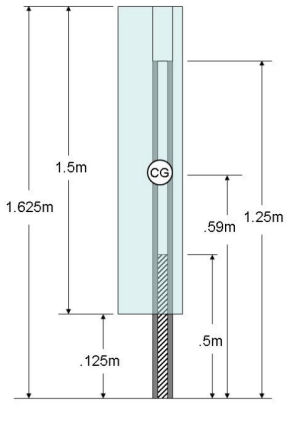
The point of reference is the center of the hub. It has to be regardless of where the blade lies. The rotational center. In the diagram the mounting stub and tube go all the way to the center which is a little different than real life but this is negligible. 1.) First step is to determine the moment of inertia for our system. This is just the balance point for all these components added together. I used standard values for the material Phill pointed out. Reference the diagram as well. Mb - mass blade = 1.75kg Rb - radius of blade center = .875m Mt - mass of tube = .912 kg Rt - radius of tube center = .625 Ms - mass of stub = 1.52kg Rs - radius of stub center = .25m The center of mass is given by the following equation; 
So the math is; R = (Mb*Rb + Mt*Rt + Ms*Rs) / (Mb+Mt+Ms) R = (1.75kg*.875m + .912kg*.625m + 1.52kg*.25m) / (1.75kg+.912kg+1.52kg) R = .596 m This means the center of mass for this whole system is .59 meters from the center of the hub. We'll get into the sub components in a minute. 2.) Now we will calculate the centripetal force of the whole blade assembly on the hub. This is what most people are doing and calling it done. We won't be done but we will start there. Turn 1000 rpm into rad/sec (w); w = rpm*pi /30 w = 104.7 rad/sec Determine Centripetal force the whole blade assembly exerts on hub (Fa) Fa = M* R * w^2 Fa = (4.182kg)(.596m)(104.7)^2 Fa = 27322 Newtons = 6142 lbf. So a blade constructed just as Phill has outlined in his posts will attempt to 'fly' away from the hub with a parting force of 6142 pounds. Not sure why others values vary so much but I am confident in these numbers. 3.) Calculate the forces that the spinning blade and tube will exert on the stub (Fs). This will tell us how much radial force the plug welds will be subjecting to while the blade is spinning. All we do is remove the stub from the previous equations and recalculate. R = (.918kg * .625m + 1.75kg * .875m) / (.912kg + 1.75kg) R = .789m Notice how the center of mass of the system has moved outwards from the center of the hub. This is because the mass of the stub is no longer included. Now we can calculate the force of the blade and tube only (Fbt). Fbt = (2.662kg)*(.789m)*(104.7 rad/sec)^2 Fbt = 23023 Newtons = 5175 lbf So the blade and tube try to leave the hub and stub with 5175 pounds of force. This might be a good thing to know when designing your plug welds, right? 4.) Calculate the centripetal force imparted by the blade extrusion only (Fb). This will tell us how much force is trying to pull the aluminum extrusion off the tube. Fb = (1.75kg)*(.875m)*(104.7 rad/sec)^2 Fb = 16786 Newtons = 3775 lbf So now we know that the aluminum blade extrusion will try to leave the turbine with a force of 3775 pounds. This is useful in determining how you need to mount the blade to the tube, rivets or adhesives. That's another discussion. To summarize: I know it's been a long post. Maybe you had to go get a beer half way through. I know I did. 1. The blade will be pulled away from the tube with 3775 pounds of force 2. The blade and tube will try to pull away from the stub with 5175 pounds of force 3. The entire hub assembly will try to pull away from the hub with 6142 pounds of force. This type of model can easily be adopted to rind the centripetal forces anywhere along this blade assembly. You can use this methodology to determine the tensile loads to suit your needs. More to come and comments/corrections welcome. Perry P.S. Let me know if you are interested in determining the centripetal loads at any particular point. |
||||
| Perry Senior Member Joined: 19/11/2009 Location: Posts: 190 |
Here are two examples to better illustrate my point. Let's get some useful information from all these formulas! Finally. Lets say you want to answer two questions of interest. what is the force on the aluminum extrusion that is totally unsupported at the tip and what is the force on the tube right where the solid bar ends. These are the highest stress positions in the design. Here is a diagram once again of Phill's proposed design as he stated it. 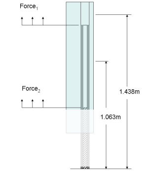
I am leaving out some of the math regarding areas/densities/and mass calculations of the components, no need to type in all the basic stuff. It's all in there though. 1.) Calculate the forces on the unsupported tip. I call this F1 in the diagram The outboard tip portion has a mass of .437kg. It's center point is 1.438m from the hub center. F1 = M*R*w^2 = (.437kg)(1.438m)(104.7 rad/sec)^2 F1 = 6888 Newtons = 1548 lbf So now we know that the unsupported tip will will be pulled with 1548 pounds of force right where the hollow tube ends. Hope it's tensile strength is good. 2.) Determine forces outboard of the solid rod. This is a little different because you now have a compound system and the masses and radii for the different materials have to be accounted for. Using the methodology in the above post we find; Mt = mass of tube outboard of solid rod = .552kg Rt = radius of center of outboard tube section to the hub center Mb = mass of blade outboard of solid rod = 1.313kg Rb = radius of center of outboard blade section to the hub center To determine the center of mass of the outboard section we have; R = (.552kg*.875m + 1.313kg*1.063m) / (.552kg + 1.313kg) R = 1.007m Now calculate the force. I call it F2 in the diagram. (total mass of this system is 1.865kg) F2 = (1.865kg)(1.007m)(104.7 rad/sec)^2 F2 = 20587 Newtons = 4626 lbf This is interesting because after the stub, or solid rod, ends the blade from that point onward is supported only by the tube. It has a very small area and since we know that; stress = force/area we can calculate the tensile stress in the tube due to centripetal forces to be 223 Mpa. Over half way to it's yield point and we haven't even added in any of the more complex forces yet like gyro and bending. So from these two posts I think we have learned the following. Pretty important information if you are designing this particular system 1.) The entire blade assembly will be pulled away from the hub with 6142 pounds of force - design hub appropriately 2.) The plug welds will have 5175 pound of shear force exerted on them - design your welds accordingly 3.) Forces will try to pull the blade off the tube with 3775 pounds of force - choose your epoxy or fastening means appropriately. 4.) The blade extrusion must be able to handle 1548 pounds of tensile pull or the unsupported tips will shed. 5.) The tubing will be subjected to 4626 pounds of tensile force at it's weakest point, just outboard of the rod - a good place to look for improvements in the design Perry |
||||
| oztules Guru Joined: 26/07/2007 Location: AustraliaPosts: 1686 |
This looks like sobering information. I will be interested in what the yaw forces bring to the system.... they are the scary part I think. Looks impressive figuring from this end. Thanks for spending the time on it. We had a spot of breeze here today, and pulled over 3000 watts on many occasions. The blades looked like they were traveling pretty quick. They took a lot of buffeting too as they are at ground level... gets a little hairy I must say. .........oztules Village idiot...or... just another hack out of his depth |
||||
| Perry Senior Member Joined: 19/11/2009 Location: Posts: 190 |
Don't get me wrong here. Nothing looks unworkable so far, with a little tweaking. Perry |
||||
| fillm Guru Joined: 10/02/2007 Location: AustraliaPosts: 730 |
Hi Perry , Thankyou , you seem to have a wealth of knowledge with mathmatical equasions and formulars . I am sure everyone here would also back me on saying thanks for your time and effort with regards to resolving the question of "Forces on a Blade" As you do not have exact weights to work with for each area and only a blade weight and rough overall weight that I took from Karls blades it does end up at a more realistic figure . As I have been more in the belief that over engineering a blade with to much weight can as detremental as to light in construction . The answer I think is to know what forces you are dealing with at a given speed , margin a safety factor of 2 or 3 and design it accordinly . As I have already been going down those lines with the blade arm mount that independantly locks the steel solid and the s/s tube with the 90deg flare ( 5T to flare the tube ) thus spreading the load and not relying on one anchor point , I am confident that it will handle the load at the hub , tests will confirm this . Keeping the weight to safe minimum at the outer sections of the blade will decrease the gyroscopic forces . Now for the head on the chopping block time , aluminium does have a tensile strength rating its a metal not plastic , when you look at the profile it has a centre web , which in my way of looking at it , is an I beam in a convex and concave aluminium skin which is double thickness on one side for the tube mount , then there is the tube mount profile . I would think this should be taken into account when deciding how far should the end be unsupported to keep the weight closer to the hub and mabe further reduce gyroscopic forces acting on the blade arm assy . Yes ,I do expect to cop some flack on that . Once again thanks Perry and Greenbelt for the time and effort put into their posts and illestrations , im sure its helping everyone to understand what forces we are dealing with .
PhillM ...Oz Wind Engineering..Wind Turbine Kits 500W - 5000W ~ F&P Dual Kits ~ GOE222Blades- Voltage Control Parts ------- Tower kits |
||||
| Gizmo Admin Group Joined: 05/06/2004 Location: AustraliaPosts: 5187 |
Just to throw another idea into the mixing pot..... Does anyone have much experience or knowledge with using solid fibreglass or carbon fibre rods? I'm wondering if it could be used instead of steel. Fibreglass, and especially carbon fibre, is very strong and light. Not as strong as solid steel, but much lighter, meaning less loading at the blade mounting and less likely to fail, maybe? http://able.en.ecplaza.net/1.asp http://www.carbonology.com/carbon-fibre-rod-section-c-28.htm l Glenn The best time to plant a tree was twenty years ago, the second best time is right now. JAQ |
||||
SparWeb Senior Member Joined: 17/04/2008 Location: CanadaPosts: 196 |
Perry, I must congratulate your effort at showing the work required to analyze the radial loads.... and as you pointed out at the end, you haven't even started on the rest of the load cases. I hope everyone appreciates the MANY hours you've spent so far on their behalf working on this one. If you are determined to pursue it to the end, then I volunteer to help with the integrals when you need the gyroscopic moment of inertia, if you want. It won't be the same as the calculation you used for the center of gravity. It goes more like: d(Im) = dM(r) * r * dr I may have missed a factor of 2 in the equation above because I'm just dredging it out of memory at the moment. My free time is limited, but if you're in this to the end, then I'll play a part where I can. Steven T. Fahey |
||||
| The Back Shed's forum code is written, and hosted, in Australia. | © JAQ Software 2026 |
