
|
|
Forum Index : Microcontroller and PC projects : Recommend a PCB Layout Tool for a newbie?
| Author | Message | ||||
| Nixie Regular Member Joined: 19/02/2013 Location: AustraliaPosts: 66 |
Thanks for your responses! A very interesting thread! 
It has certainly given me more to think about in terms of the effort and cost benefit of making PCBs on a CNC machine. I won't be getting one! I too will stick to the tried and tested laser printer method, though some of the references above have led me into different ways of impressing the layouts onto pre sensitised PCBs and the different types of plastic sheets that are being tried. See: http://hackaday.com/2012/12/10/10-ways-to-etch-pcbs-at-home/ http://dangerousprototypes.com/2012/09/29/pcb-manufacture-us ing-oracal-vinyl-film-laser-printer/ Cheers all, Nic VK3COW |
||||
bigmik Guru Joined: 20/06/2011 Location: AustraliaPosts: 2981 |
Gday Lads/Lasses, I have still been arm wrestling with Protel99se and Windows 7 (incompatible and needs hacking to get libraries to work) and looked at eagle but it didnt suit me and I found it clunky.. I have just come across this AUTOTrax DES (NOT related to Protels autotrax from the 1990's) AutoTrax DES I found the Link from Dave Jones EEVBlog site and I have to say it looks very interesting... They have the price on special at the moment for $49US (down from either $99 or $199, depending on what site you look at ... it seems they are playing with their pricing) I have played with the demo and I find it rather neat and not much different from what I am used to in Protel99se, The differences are, IMHO better than Protel99se/ Before I jump, has anybody else played with this program? On EEVblogs forum there is a lot of comments about the software being good but some bad comments as some people/person didnt like the fact it was written by only one person instead of a team of people... Also a couple of people couldn't get it to work but had difficulty convincing them for a refund. That may have been an earlier version as this is a new release now. Baring the above negative comments it really does seem a very good PCB program and $49 for a FULL version is a great price. Any Comments? Regards, Mick Mick's uMite Stuff can be found >>> HERE (Kindly hosted by Dontronics) <<< |
||||
| vasi Guru Joined: 23/03/2007 Location: RomaniaPosts: 1697 |
Hi Mick, Have you tried DipTrace? Hobbit name: Togo Toadfoot of Frogmorton Elvish name: Mablung Miriel Beyound Arduino Lang |
||||
| bigmik Guru Joined: 20/06/2011 Location: AustraliaPosts: 2981 |
Hi Vasi, To be Honest NO.. I looked at Eagle but didn't like it (In fact I hated it) as it was a very popular program... The deal is on until 15th March so I will have a look at diptrace first. The thing I like about AutoTrax is it is so close to Protel99se in appearance the schematics are great (I hate the eagle schems... they are ugly and hard to follow) I played with the schematic and it has some nice features like the little bridge jumps over lines that a cross-over line is Not supposed to connect to.. and little blobs where they are meant to connect.. Just like I first learned to draw schematics about 150 years ago... 
I was wondering if anyone here has actually used Autotrax DEX. Regards, Mick Mick's uMite Stuff can be found >>> HERE (Kindly hosted by Dontronics) <<< |
||||
| vasi Guru Joined: 23/03/2007 Location: RomaniaPosts: 1697 |
I didn't worked with it. I watched now few videos and schematics looks indeed very nice (I also like schematics made in KiCAD). The 3D part is horrible. It looks better on DipTrace. I'm not scared by "unfriendly" programs and I adapt very well to any work flow so I can work in Eagle, KiCAD and gEDA. But I can say that I never found a program as easy and intuitive as DipTrace. Try it. You will not like too much the looks of the schematics, but I assure you that it will fully compensate with the speed in designing your project. Unfortunately for me, there are two reasons I don't use it as it deserves: - no linux version; - in Eagle (with some scripts help) I can generate excellent 3D images, very good for illustrations, documentation and advertising like the one bellow: 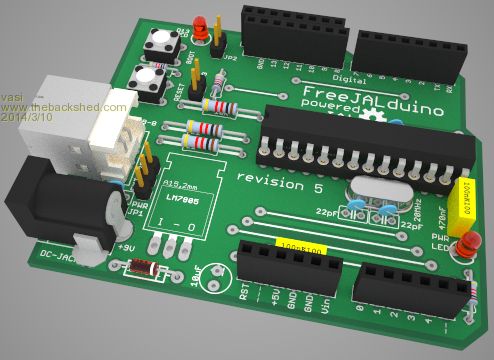
But you can get good 3D images with DipTrace too: http://www.thebackshed.com/forum/forum_posts.asp?TID=4841&PN =6 Hobbit name: Togo Toadfoot of Frogmorton Elvish name: Mablung Miriel Beyound Arduino Lang |
||||
TassyJim Guru Joined: 07/08/2011 Location: AustraliaPosts: 6538 |
That was enough for me to download the demo. I have Protel Easytrax from a long tome ago and at a price that frightens me. First impressions: The demo circuit has a few errors. I haven't looked at the layout to see if they are carried through and I need to see if any checking should have found them. No scroll bars when you zoom in - you have to use the arrow keys. It took me a while to find where you can save a schematic as an image. I am currently installing the library and reading the 600 page manual. $50 US is a reasonable price if it does the job. I an tempted. Jim VK7JH MMedit |
||||
| bigmik Guru Joined: 20/06/2011 Location: AustraliaPosts: 2981 |
Vasi, I agree the eagle 3D looks better but in all honesty I have never needed nor wanted 3D and even though Protel99se has 3D.. I want nice, readable Schematics and good artwork.. That aside it does have some interesting 3D views, like transparent PCB so you can see through the Board for both layers and components and a "stretch mode" so you can see internal layer connections... Jim, Yes you pan with the arrows and zoom with the mouse wheel.. I found that a heap better than the Protel99se methods (Click zoom button and use arrows). There may be other methods but I havent looked that closely yet. Which errors did you see? I saw short tracks but I think it was that they ended in a via which was probably set to be very small (I generally use .050" dia (1.25mm) Via I think his were set to something like .030" or .75mm... Otherwise I found the examples very good.. Have a read of the forum on EEVBlog Forum It goes back to 2012 and is about 18mths old but there are quite a few updates since then that may have corrected the issues that some people had. There was also mention of it being a 12mth subscription to updates but I have an email from Iliya stating it is a full program and you get updates only for the 12mths and the program will still work beyond the expiration of the 12mths (and can be reinstalled on another PC). I dont really like that type of update bit (upgrade to a newer version YES but updates are generally minor) but then it is very cheap for a full function non restricted license. Regards, Mick Mick's uMite Stuff can be found >>> HERE (Kindly hosted by Dontronics) <<< |
||||
| TassyJim Guru Joined: 07/08/2011 Location: AustraliaPosts: 6538 |
The interwire connectors that link the RS232 input to the CPU have wrong labels. The CPU end is OK - M8TXD and M8RXD but the other end they are both M8TXD. On the PCB, it follows the schematic - both R8 and R5 connected to M8TXD Diode D31 is a type 1nF. (Being picky there, I know) Discovered an interesting effect - try changing from Imperial to Metric and back again. A lot of the nice lines are now up the creek. None of the above are show stoppers for me. Jim VK7JH MMedit |
||||
| Warpspeed Guru Joined: 09/08/2007 Location: AustraliaPosts: 4406 |
I believe the first original DOS based Autotrax pre dated Protel. I still have copy here somewhere, along with Traxplot the companion plotting software. Protel being a later and much more professional package. Like yourself I have used various releases of Protel professionally for many years. Even did the official Protel two day course paid for by my employer (fortunately). Before the entire circuit board manufacturing industry in Australia went collectively bankrupt, Protel was pretty much universal everywhere in Australia. For home use, Protel was priced way out of the market, (about $3,000 if I remember) so they seem to have gone back full circle to their original Autotrax roots with something a lot more affordable for home use. Being retired, I have not used either for a very long time, but Protel/Autotrax have been in the game for a very long time, so I would expect their latest software to be both bug free and user friendly, although I have not tried it. Cheers, �Tony. |
||||
elproducts Senior Member Joined: 19/06/2011 Location: United StatesPosts: 282 |
I like to use ExpressPCB and their low cost prototype option but I know shipping can cost a lot for outside USA. They also offer the gerbers for $60 after you create your prototype boards. But that gets expensive fast. David Cook created and released CopperConnection because he was tired of waiting for ExpressPCB to release new updates and he wanted gerber output. What he created is a very useful PCB creation software. It can import ExpressPCB files directly and then give you more features to work with. You can print directly for toner transfer. And all this is a free download except for the gerber feature. For a one time $50 upgrade fee for the Pro version you can export all your designs to gerber and have your boards produced wherever you want. So it allows me to use my familiar ExpressPCB software and the extra features of CopperConnection and now I can get boards produced anywhere without the extra $60 every design. CopperConnection Just another option to consider especially if you are already an ExpressPCB user. www.elproducts.com |
||||
| bigmik Guru Joined: 20/06/2011 Location: AustraliaPosts: 2981 |
Hi Tony, Yes my employer bought Protel98 then upgraded to 99se... I use it at work I know they paid about $4k for the package originally ... not sure about the upgrade.. Not cheap. I used SMARTTRAX(??) then Autotrax in early 90's I used to print 2x size on a dot matrix printer and reduce to single photographically.. worked well. Autotrax DEX is no relation to autotrax but has some similarities with Protel but the more I play the less its like Protel.. I have found a very concerning problem with Autotrax DEX that worries me somewhat.. If you load the Arduino sample.. and unroute all the tracks then route them all a few connections dont route unless you select ELECTRA routing which costs an arm and three legs to purchase from a 3rd party company.. Also some connections seemed too close to pads and it laid out some weird tracks at times. If the standard router doesnt route then its of no use to me.. I will still play a bit more with it... it might be something to do with grids as it was the DB9 connector that doesnt route. Regards, Mick Mick's uMite Stuff can be found >>> HERE (Kindly hosted by Dontronics) <<< |
||||
| Warpspeed Guru Joined: 09/08/2007 Location: AustraliaPosts: 4406 |
Mick, I have never liked autorouting, some of the early ones were pretty hopeless and unusable anyway. There is a lot more to it than just linking up net lists in an arbitrary way. All sorts of other considerations such as grounding, high current tracks, high frequencies and high impedances, induced noise, leakage effective bypassing minimising EMC radiation and so on. The schematic is only half of it, very poor PCB layout can doom even a really good design. It may seem mad but I do everything in the exact reverse manner. First lay out my entire board manually. Then work out the component designators, and go back and add those to the schematic. The software then creates a net list, and a bill of materials, and any errors to those are then fixed. The autoroute looks at the already completed board and either says "done" or points out any errors. The advantage is the component designators on the board are then all laid out logically. R1 is right next to R2, and C45 and C46 are right next to each other. Nothing worse for the service tech with his probe in his hand trying to find R96 on a really large board when it could be located absolutely anywhere on the board. Cheers, �Tony. |
||||
| paceman Guru Joined: 07/10/2011 Location: AustraliaPosts: 1329 |
Tony, 'Doing it backwards' rings true to me and is an interesting observation from a professional. I'm very amateur at this but I'm setting myself up to make PCB's and am learning to use DipTrace, (which seems to me to be a pretty logical tool, free and quite comprehensive). I think your 'doing it backwards' comment can go even further in that I've found that deciding what sort of box you're going to put your project in, almost needs to be the first step. The box dictates a lot of how the whole project has to be laid out, PCB size, connector location, box (or chassis) mounted bits and pieces. Greg |
||||
| Warpspeed Guru Joined: 09/08/2007 Location: AustraliaPosts: 4406 |
Oh yes ! PCB size and where the existing threaded holes are located in the plastic box. Then place your ICs so the input and output pins of each chip are at least somewhere near where they need to go. Then start looking what is going to be the most hairy and potentially troublesome part of the circuit as far as layout goes. Maybe the switching power supply, or the very high megacycle clock, or some microvolt sensitive analog circuit, or maybe all three that have to live happily together. Build it up logically, and move stuff around so it all fits neatly into whatever space you have. No automatic router comes even close to having the knowledge and experience you yourself can put into it with a bit of thought and pre planning. Cheers, �Tony. |
||||
| MicroBlocks Guru Joined: 12/05/2012 Location: ThailandPosts: 2209 |
I use diptrace, first the free version. After a while i bought it. Price is good. I always start with a schematic, then manual placement and manual routing of critical traces, lock those and let the autorouter give it a go. Simple boards are done pretty quick this way. When it gets more compact/complicated the autorouter does not produce the quality i want and i either route everything by hand or modify the auto routed result. Renumbering the parts on the pcb is easy and then back annotate it to the schematic. Microblocks. Build with logic. |
||||
| Warpspeed Guru Joined: 09/08/2007 Location: AustraliaPosts: 4406 |
There is a trick to doing it that way. When you draw your original first schematic, start off with the first resistor being maybe R100, and the first capacitor being C100, or C50 or something. The software will then automatically designate the second resistor you want to place as being R1 (next unused designator in sequence), and you immediately edit that to R101 on the schematic. Finish drawing your schematic with all the component designators being extra large numbers. Route your board either manually, or automatically, (or a mixture of both). When the board layout is complete, you can then edit the components on the board knowing that you can make the first resistor R1 without getting an error message saying R1 already exists somewhere else on the board ! Its a lot of work going back editing component designators, but if you use this method it avoids creating one huge tangle of error codes. Cheers, �Tony. |
||||
| MicroBlocks Guru Joined: 12/05/2012 Location: ThailandPosts: 2209 |
I use the automatic RefDes renumbering feature. Works very well. Manually renumbering works also easy, if another component has already that number you get a warning and can choose to shift the conflicting part up in numbers. You do need to remember to back annotate otherwise the schematic and pcb are out of sync. Diptrace does not do that automatically, which both can be a feature or shortcoming depending how you like it. In practice i not even look at the numbering in the schematic. The above described process just takes a few seconds and i do it when the PCB is ready. Microblocks. Build with logic. |
||||
| JakeStew Newbie Joined: 02/12/2012 Location: United StatesPosts: 11 |
Seems like there is a plethora of dead-end oldschool and new upstart programs that just aren't there yet. Still nothing really comes close to Eagle as far as real world results. |
||||
Grogster Admin Group Joined: 31/12/2012 Location: New ZealandPosts: 9975 |
I use Sprint Layout 6, and love it. My 2c only. Smoke makes things work. When the smoke gets out, it stops! |
||||
| vasi Guru Joined: 23/03/2007 Location: RomaniaPosts: 1697 |
Is an entire ecosystem around it (suppliers, PCB houses, open projects, etc.). With a lot of tested components. That is why you can't ignore it. At least, for his library which can be imported in other EDAs. But the scripting engine is also a plus - among other nice tools, a g-code exporter is possible because of this. And a good advertising of Eagle for the hobby zone is this great movie: https://www.youtube.com/watch?v=w4Ypo_4zHvo Hobbit name: Togo Toadfoot of Frogmorton Elvish name: Mablung Miriel Beyound Arduino Lang |
||||
| The Back Shed's forum code is written, and hosted, in Australia. | © JAQ Software 2026 |
