
|
|
Forum Index : Microcontroller and PC projects : External watchdog chips...
| Author | Message | ||||
bigmik Guru Joined: 20/06/2011 Location: AustraliaPosts: 2981 |
The price here (Australia) is only $3.25AU in one off (inc free postage) from RS components ($2.56AU in 25off QTY) And 101 Bhat from their Thailand store (about $3.45AU) in 1 off. And $4.68NZ from their New Zealand Store RS-Price Regards, Mick Mick's uMite Stuff can be found >>> HERE (Kindly hosted by Dontronics) <<< |
||||
| bigmik Guru Joined: 20/06/2011 Location: AustraliaPosts: 2981 |
Hi Groggy, I had a look at the CCT in question and I think that if you add one capacitor to the mix you may be able to trigger the timer on power up and keep the output high for 1 time cycle. See the cct below.. I am not sure what value but you could experiment starting with 1uf and go up and down as required.. 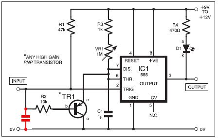
Regards, Mick Mick's uMite Stuff can be found >>> HERE (Kindly hosted by Dontronics) <<< |
||||
Grogster Admin Group Joined: 31/12/2012 Location: New ZealandPosts: 9975 |
@ Mick - thanks very much for the RS link! 
I have not ordered any yet, so this will be the place I will get them from - much better price then Element-14, which are not known for the best prices on some things. 
And on the 555 circuit, I will try that, and let you all know - thanks for the hint. I have pulled the circuit to bits now, but I can rebuild it on the breadboard in a few minutes... I guess we still have an issue in that the 555 circuit needs at least 4.5v to operate, and I am pretty sure that the PIC32 reset pin is NOT 5v tolerant, and more then 3v3 on it's reset pin will probably kill the PIC32, so the 6369 chip might well be the best option, albeit with it's tiny pin spacing, as you can run it right down to 2.5v. Smoke makes things work. When the smoke gets out, it stops! |
||||
| bigmik Guru Joined: 20/06/2011 Location: AustraliaPosts: 2981 |
Hi Groggy, No problems, pleasure to be useful for a change... 
No worries, Maybe the cap might work better on the other side of R2, trial and error here.. It would probably lengthen the strobe pulse so bear that in mind... Of course you could route through a transistor switch, I can provide a cct for that if you need it, that switches between 0V and 3.V. Regards, Mick EDIT ** Or maybe just 2 standard diodes in series on the output might work as well, they will drop 0.6V each and turn 4.5V into 3.3V Mick Mick's uMite Stuff can be found >>> HERE (Kindly hosted by Dontronics) <<< |
||||
| Grogster Admin Group Joined: 31/12/2012 Location: New ZealandPosts: 9975 |
Please feel free to post your extras including the transistor switch. Not sure the series diodes would work, as while they would drop the voltage to the reset line, they will block the 555's attempt to pull the reset line low, would they not, as they would be reverse biased? I would be running the 555 circuit from 5v. I am guessing that your transistor idea would be the best option. PNP type, emitter to PIC32 reset, collector to deck(ground), 1k base-loading resistor to 555 output. That way, when 555 output is high, PNP would be off, allowing PIC32 to run. When 555 output goes low, PNP will pull reset line low via C-E path, resetting the PIC32. Smoke makes things work. When the smoke gets out, it stops! |
||||
| bigmik Guru Joined: 20/06/2011 Location: AustraliaPosts: 2981 |
Quite right! 'Sorry about that Chief' Here is a possible cct for the output of the 555 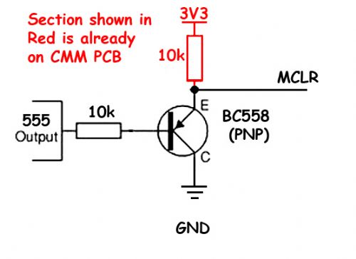
Regards, Mick Mick's uMite Stuff can be found >>> HERE (Kindly hosted by Dontronics) <<< |
||||
| MicroBlocks Guru Joined: 12/05/2012 Location: ThailandPosts: 2209 |
You can also just use a 3v version. :) I am organizing my datasheets and putting them online so if i find it, i'll let you know. Microblocks. Build with logic. |
||||
| Grogster Admin Group Joined: 31/12/2012 Location: New ZealandPosts: 9975 |
You mean a 3v 555? Smoke makes things work. When the smoke gets out, it stops! |
||||
| bigmik Guru Joined: 20/06/2011 Location: AustraliaPosts: 2981 |
I think he means the LMC555... The CMOS version... I think it will work down to about 1.5V. Regards, Mick Mick's uMite Stuff can be found >>> HERE (Kindly hosted by Dontronics) <<< |
||||
| MicroBlocks Guru Joined: 12/05/2012 Location: ThailandPosts: 2209 |
I found the data sheet of the 3V 555 timer chip again. Here it is: http://tzblox.com/documents/data_sheets/STMicroelectronics/T S3V555%203V%20Low%20Power%20Single%20Timers%20-%204075.pdf I looked in my part inventory but i don't have them anymore. It should be an inexpensive part. I will try to find where these are for sale. Microblocks. Build with logic. |
||||
| bigmik Guru Joined: 20/06/2011 Location: AustraliaPosts: 2981 |
Hi TZ, Except that part is now Discontinued.. 
Regards, Mick Mick's uMite Stuff can be found >>> HERE (Kindly hosted by Dontronics) <<< |
||||
| vegipete Guru Joined: 29/01/2013 Location: CanadaPosts: 1180 |
Seems to me that a PIC10F200 would be a good candidate for an external watch dog timer chip. Cheap, works down to 2 volts, no external components required and can be programmed with whatever characteristics the system needs. (And it has its own internal watch dog... ;-) Visit Vegipete's *Mite Library for cool programs. |
||||
| MicroBlocks Guru Joined: 12/05/2012 Location: ThailandPosts: 2209 |
Problem will always be when a PIC is used to perform a watchdog function it can itself go wrong. You would then need a watchdog to watch over it. If it is the internal watchdog it can trigger and reset the Watchdog PIC, by that changing the output ports and put the main circuit in reset. This is just adding a new point of failure instead of making it more secure it will be less secure. Even a 555 would then be better. It has a much lower chance of running amok because some software bug or a fault in internal peripherals and function blocks within a micro controller. It would be such a shame when a circuit fails because the watchdog is not good. Microblocks. Build with logic. |
||||
| Grogster Admin Group Joined: 31/12/2012 Location: New ZealandPosts: 9975 |
@ bigmik and TZA - Perhaps then, the 7555? This is SOIC like I want(not too small for me to solder!), and only NZ$1.50. Might have to check the RS components price, but for a buck fifty... (US$1.16) @ vegipete - thanks very much for the link. However, we have tossed around the idea of using a PIC as a programmable watchdog, and this is certainly one option, but at this stage, I am wanting a WDT that is NOT another MCU, so that(to paraphrase MOBI for a moment) we don't have the situation of the blind leading the blind, if the WDT PIC was to crash for some reason. However, this idea(of using a PIC) is becoming more and more attractive to me due to simplicity and the fact you can program the thing to act as a WDT exactly to your own requirements. That, and the fact that I have used a couple of hundred PICs to date, and none of them have ever crashed, once the code was bug-free... I have just to test out 555 alterations above, then I will decide what to do. Smoke makes things work. When the smoke gets out, it stops! |
||||
| Grogster Admin Group Joined: 31/12/2012 Location: New ZealandPosts: 9975 |
The full size DIP is even cheaper at NZ$1.18, which is US 93 cents. DEFINITELY have to check this idea out some more, as I can then run the CMOS 555 at the PIC32's 3v3 core voltage, and connect directly. I will now build the modified 555 circuit, and see what happens. The tinkering continues... Smoke makes things work. When the smoke gets out, it stops! |
||||
| MicroBlocks Guru Joined: 12/05/2012 Location: ThailandPosts: 2209 |
If you can use the discharge as the output you can connect it directly to the MCLR. If you look on page four of the datasheet you can see that the output is a pull-push type and the threshold an open-drain. Not needing a transistor saves pcb space and is cheaper. Microblocks. Build with logic. |
||||
| Grogster Admin Group Joined: 31/12/2012 Location: New ZealandPosts: 9975 |
@ TZA, yeah, I see that too, but I was looking at the full schematic at the top of page 5... I will build the standard 555 circuit again, and see what happens with the extra cap suggested by Mick, just using LED's as the original circuit shows, and not connected to the PIC32 yet. If I can get the 5v version working OK, then I will plop in a 7555 and lower the voltage to 3v3, and also still on LED's, see what happens. In that circuit, they have connected discharge to the E of the PNP input transistor among other things, and I am guessing that I can't just disconnect discharge from where it is, or the circuit will most likely stop working. At the lower voltage, I am also guessing that the time interval will be longer - I will keep the thread posted on what happens. Smoke makes things work. When the smoke gets out, it stops! |
||||
| Grogster Admin Group Joined: 31/12/2012 Location: New ZealandPosts: 9975 |
Kudos to Mick - he was really on to something with that cap. 
I added a 1uF and now the 555 output is high on power-up for the first time cycle. I actually lowered the value of the cap down to 100n, and it still works great. I think I will still use 1uF on the final design though, unless someone else here can suggest why that would not be a good idea. Perhaps 470n? - somewhere in the middle... I will now swap the 555 for a 7555 - but I have to drive to town to get a couple of these, as I only have the standard 555's here. Once I have them, I will plop the 7555 in there, and then start playing with 3v3 and cap values etc. I plan to use a tantalum in the final version, for the timing capacitor, to keep the time period reasonable stable over time.(if you'll pardon the pun there...) PROGRESS!!!! Smoke makes things work. When the smoke gets out, it stops! |
||||
| Grogster Admin Group Joined: 31/12/2012 Location: New ZealandPosts: 9975 |
Kudos to TZA now!
If I remove the LED on the 555 output(and it's resistor), and move these to the discharge pin(LED's load resistor still to 5v, LED cathode to the discharge pin), then the LED still comes on after the time-out period - perfect.
I have settled on a 470n cap on the input transistor a-la Mick's idea. I removed the link between discharge and threshold - the rest of the circuit is still the same. I will post the circuit soon, so everyone can compare notes. The only issue left now, is that once tripped, the 7555 will hold the PIC32 reset low, and the chip will never restart. This is not a new problem, it was always there, but I am having a think on how we can fix that along the lines of another transistor on the supply to the 7555 circuit, so that when the output trips, the transistor switches off the 7555 - which promptly restarts, because the transistor holding it off, has lost it's base voltage, which was coming from the 7555, if you see what I mean... Adding a cap on the base of the switching transistor would control the length of the pulse. This should give a singular reset pulse at the end of the time-out, but then the LED should go out again until the next time-out. All very much in theory at the moment, so we'll see what the breadboard makes of my idea.
...still a bit more tinkering to do... Smoke makes things work. When the smoke gets out, it stops! |
||||
| bigmik Guru Joined: 20/06/2011 Location: AustraliaPosts: 2981 |
Hi Groggy, A pleasure mate... Did you move the cap to the Transistor side? (I think it would be better there)... And I just took a guess at a suitable start value... On your observations I would probably go with 220-470nf... Try adding a 22k resistor from the 555 output to the input of the 555 cct to re-trigger the count... This value cant be too low else the MCLR line will fall below its trigger level (10k UP with 22k down) and will cause the PIC to reset every time the input gets pulsed... Regards, Mick Mick's uMite Stuff can be found >>> HERE (Kindly hosted by Dontronics) <<< |
||||
| The Back Shed's forum code is written, and hosted, in Australia. | © JAQ Software 2026 |
