
|
|
Forum Index : Microcontroller and PC projects : MicroMite 44 Pin TQFP Eval PCB/Module
| Author | Message | ||||
| WhiteWizzard Guru Joined: 05/04/2013 Location: United KingdomPosts: 2991 |
Thats ok Grogster 
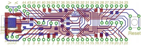
Note that following: - Pin 6 or Pin 16 need to be connected to GND (no need for both as these pins are connected to each other on the PCB) - Likewise, Pin 29 or Pin 39 to GND - Likewise, Pin 17 or Pin 28 or Pin 39 to +3v3 - not sure if 100% stability is achieved without any decoupling caps so have included the ability to add 3 x 100nF on each of the power inputs (I always include all three simply to meet data sheet specifications - not really a space demand for this PCB, and near zero cost!) - 10uF-47uF tant on Pin 6 & Pin 7 is a must! - Don't forget a 10K resistor between Pin 18 & Pin 19 when incorporating ICSP - Do you think I should include this on the PCB? Let me know if you have any problems . . . |
||||
| WhiteWizzard Guru Joined: 05/04/2013 Location: United KingdomPosts: 2991 |
ERROR Oohps! Make that Pin 17 or Pin 28 or Pin 40 
Sorry! |
||||
Grogster Admin Group Joined: 31/12/2012 Location: New ZealandPosts: 9975 |
As that resistor is pretty much standard, I would be inclined to include it - it's a matter of opinion.  Smoke makes things work. When the smoke gets out, it stops! |
||||
| WhiteWizzard Guru Joined: 05/04/2013 Location: United KingdomPosts: 2991 |
Grogster, 
Now its not so pretty! 
Heres the mod: 2014-02-10_062013_MicroMiteDIPv3.brd.zip Let me know if you are able to open the file successfully as I'm on an iMac and it keeps saving it as a windows file  Thanks! Thanks! |
||||
| Grogster Admin Group Joined: 31/12/2012 Location: New ZealandPosts: 9975 |
Looks pretty enough for me.
EDIT: Opens fine in Eagle for me.... Smoke makes things work. When the smoke gets out, it stops! |
||||
| WhiteWizzard Guru Joined: 05/04/2013 Location: United KingdomPosts: 2991 |
Eagle files to make Eval PCB/Module 
I keep getting a 'Bill Gates' error when generating the Gerber Files so to avoid any more delay I have attached the actual Eagle files: 2014-02-11_010903_MicroMite_v3.brd.zip Component values are included within the file but please feel free to contact me if you need any help! For anyone just wanting a single sided PCB comprising of simply a 44 pin DIP (i.e. no USB or ICSP circuit) then here it is re-posted: 2014-02-11_011112_MicroMiteDIPv3.brd.zip 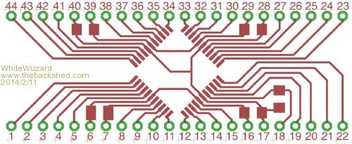
For those of you that don't have the Eagle software, download a light version for free from the following link: Free EAGLE download Please let me know if a circuit diagram is required! I don't currently have an electronic copy so it will take a couple of hours to produce . . . . Regards, Phil |
||||
| MicroBlocks Guru Joined: 12/05/2012 Location: ThailandPosts: 2209 |
Nice compact boards. 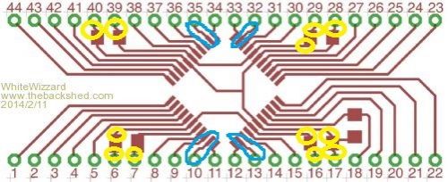
I would suggest looking at the traces i circled in yellow. Those traces connect with a very sharp corner to the pads. Most PCB houses suggest to prevent this as it can cause 'peelables'. Page 11 point 10: eurocircuit pcb design rules. Their automated system will reject those traces. The traces marked with blue could be straight. Allowing the traces next to it to be a little longer before they go into a 45 degree corner. Personally i would make the traces the same width as the 44pin pads,but only when it is manufactured with a soldermask. Microblocks. Build with logic. |
||||
| Zonker Guru Joined: 18/08/2012 Location: United StatesPosts: 772 |
Hey Whitewizzard... Good evening fine Sir.. I was looking over your artwork and noticed you were shorting pin 4 of the USB connector to ground. I was told that doing so would enable the USB OTG mode for the port and would cause problems. Maybe the FTDI chip you has this but I don't think so.. Not sure what to think about this.. Maybe look at the Doc's.. Let me know what you think about this... Thanks..!!
|
||||
| JTR0701 Regular Member Joined: 10/07/2013 Location: AustraliaPosts: 71 |
No body said it would enable USB-OTG mode or cause problems. In fact the pin may or may not be connected to ground (or have a specific voltage set via a resistor divider inside the B side connector.) The point is that USBID is an OUTPUT from the B side connector and it has no role or function when the USB is configured in device mode only as it is with the FTDI chips. |
||||
| WhiteWizzard Guru Joined: 05/04/2013 Location: United KingdomPosts: 2991 |
Hi Zonker, Good to hear from you.
When I attended a USB course at Microchip's Head Office last year I remember there being quite a debate about the topic of grounding USB Pin 4. Surprising how many attendees were getting defensive about their own reasons for grounding it (or not)! Personally I have seen so many professional designs - some with it grounded (for non OTG devices), and some with it not grounded. I have always taken the route of grounding it and because I have never experienced any problems I continue to take this route without really thinking about it. So thanks for raising this potential error, and to clarify for certain, I will google some 'official' docs and will come back to you with my findings. Please don't delay your initial batch of your excellent board because of this matter (I have just read your thread). If designs demand Pin 4 to be grounded for whatever reason then I will let you know the source of the data and you can decide to modify you pcb for any future batches. One thing for sure - your board will work whether it is grounded or not! Regards, Phil |
||||
| Zonker Guru Joined: 18/08/2012 Location: United StatesPosts: 772 |
Thanks for your feedback Phil..! I just wanted this issue not to be a show stopper for the board... I did know one thing for sure.. I don't know anything about the USB part of things and was just following along with what I saw everyone else doing..!! 
Thanks for your knowledge on this..! |
||||
Lou Senior Member Joined: 01/02/2014 Location: United StatesPosts: 229 |
- Don't forget a 10K resistor between Pin 18 & Pin 19 when incorporating ICSP - Do you think I should include this on the PCB?
I would put it on the PC board, and I think it's on pins 17 and 18, not 18 and 19. Microcontrollers - the other white meat |
||||
| WhiteWizzard Guru Joined: 05/04/2013 Location: United KingdomPosts: 2991 |
Typo error - correct on PCB layout (thankfully!) |
||||
| WhiteWizzard Guru Joined: 05/04/2013 Location: United KingdomPosts: 2991 |
Hi All, Please can any of you out there that have used iTead for PCB production please let me know what timescales you experienced (i.e. time from ordering to receiving PCBs). If you have used them more than once, then please let me know the longest & shortest timescales (as well as the typical time if they are your regular supplier). And finally, has anyone placed a 'high quantity' order with them (>100 for a single PCB design)? If so, is there a significant change in quality? Thanks for your feedback . . . . |
||||
| MicroBlocks Guru Joined: 12/05/2012 Location: ThailandPosts: 2209 |
Only small batches. I am in Thailand so i am happy if it arrives within a few weeks. They send it quicker, the delay starts often at the border. Quality is very good. Microblocks. Build with logic. |
||||
| Geoffg Guru Joined: 06/06/2011 Location: AustraliaPosts: 3362 |
I use iTead a lot and for small quantities of PCB's they generally have them out the door in 3 to 4 days. Their quality is excellent and I am happy to recommend them. Geoff Geoff Graham - http://geoffg.net |
||||
| WhiteWizzard Guru Joined: 05/04/2013 Location: United KingdomPosts: 2991 |
I have finally made all the required changes to the 44-pin Eval PCB and am about to place an order with iTeadStudio.
However, it is very late here, I have been in front of the screen for many hours now, and I really could do with some extra sets of eyes to have a look over what I have done. 
Hence can I please ask all you wonderful people with Gerber Viewers to run your eyes over the attached files to spot any obvious mistakes! 2014-02-18_041737_MicroMite_v1.zip I have built several prototypes so I know the circuit design is robust - I am more concerned with the files themselves (i.e. missing files, incorrect format, spelling, etc) Many, many thanks in advance for your help . . . . |
||||
| Grogster Admin Group Joined: 31/12/2012 Location: New ZealandPosts: 9975 |
Very sexy indeed.
Imported fine into Sprint Layout 6, but no drill-data.
I think that is about the only missing file - everything else seems to be there. EDIT: Some silkscreen missing from some of the copper2(bottom layer, GBO file)? Some pads don't have any indication caps etc are supposed to be there? See image below - I have put ??? beside pads I thought were supposed to have some kind of silkscreen ID... 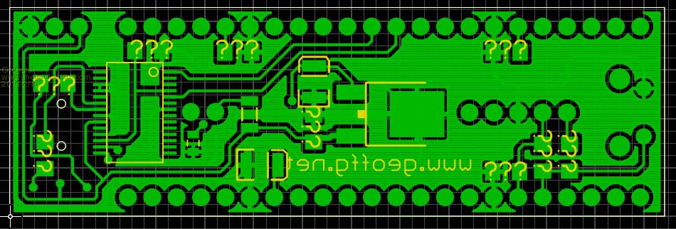
Smoke makes things work. When the smoke gets out, it stops! |
||||
| Zonker Guru Joined: 18/08/2012 Location: United StatesPosts: 772 |
You bet Wiz... I will have a look after work tomorrow... I found an online Gerber Viewer program you could try and see if it renders well... But, I agree, after someone puts something together, it's better if others have a look... You have been staring at it to long... I downloaded your .BRD file after installing Eagle-6.5 at LOU's house and brought up your design... It seems you made your board using no schematic... Just tracks and (I guess) big vias for the holes and a single footprint of the TQFP-44.. Humm... Are the SMD pads for the caps/resistors just rectangles..? You can set your hole size to 0.035 and create a CAM file to make the EXEClLON drill control file if it's missing from the ZIP.. Don't know cause I haven't donloaded it yet.. Man, almost 11:30 here... Gota get some gip... |
||||
| Grogster Admin Group Joined: 31/12/2012 Location: New ZealandPosts: 9975 |
No programmer header pin1 marker on top silkscreen. I would put the word "RESET" beside the reset button. You have not put your name(real or codename, company or other) anywhere on the board!  Smoke makes things work. When the smoke gets out, it stops! |
||||
| The Back Shed's forum code is written, and hosted, in Australia. | © JAQ Software 2026 |
