
|
|
Forum Index : Microcontroller and PC projects : 8, 14 & 18 pin DIL versions of 170 uM...
| Author | Message | ||||
Grogster Admin Group Joined: 31/12/2012 Location: New ZealandPosts: 9975 |
FANTASTIC - Why don't you do one and pop up an image!  Smoke makes things work. When the smoke gets out, it stops! |
||||
| Grogster Admin Group Joined: 31/12/2012 Location: New ZealandPosts: 9975 |
The original idea was 8-pin DIL version, but I was not convinced I could make it fit - I am still waiting for Mick to post his image, as he had some ideas, and has had more double-sided PCB design practise then me! I'm quite new to DS boards - I only ever used to do singles, but the iTead studio price for DS boards is just too good NOT to start teaching myself DS board layouts.
As for not including the programming pins and just using PCB lands - that is a nice idea, actually. I included them as pins by default, as it would making programming the firmware, then the MMBASIC program into the thing easy. However... Smoke makes things work. When the smoke gets out, it stops! |
||||
bigmik Guru Joined: 20/06/2011 Location: AustraliaPosts: 2981 |
Hi Grogster, I agree with TZ that it NEEDS to be a standard 0.3" footprint. Also dont be waiting too much on me, it is really starting to heat up at work, getting into Melbourne's big spring acing season again, I was never intending to put the program pins out to the pins.. I actially have a 5 pin ICSP header at the moment and the board is still small... I hope to have a better play around tomorrow.. As to experience doing DS boards well I think your offerings are quite good and no embarassment to you.. I find these days I have made more stupid mistakes than I have in the entire time I have been doing PCBs ... About 20 years or so.. I dont know if that is because I am getting old or that it is now so cheap, it used to cost an arm and a leg to get a PCB done, i remember setup costs of around $380 before you got to start any boards which was a panel cost... You made CERTAIN your board was correct back then.. Now with iTead etc.. What does it matter? Regards, Mick Mick's uMite Stuff can be found >>> HERE (Kindly hosted by Dontronics) <<< |
||||
| Grogster Admin Group Joined: 31/12/2012 Location: New ZealandPosts: 9975 |
Crikey - $380 setup costs - wow! 
But then, as you say - that was then, and this is now, but still...... As the PGD and PGC can be standard IO pins once programming is complete, I did not think that putting them on pins was a "Bad" idea, per-se', as once the firmware is in there, these pins become standard pins you can use - my 2c only. I am having another more intensive look at forcing the standard 8-pin footprint as discussed before. I have not submitted the PCB's yet. Smoke makes things work. When the smoke gets out, it stops! |
||||
| bigmik Guru Joined: 20/06/2011 Location: AustraliaPosts: 2981 |
Grogs, All, Has interest in this died down? I have been a bit busy but I have found time to play.. We can do this.. it is a SSOP '170 on a 15mm x 15mm PCB (and it is TIGHT) some clearances are pushed to the limits.. There seems to be some bug in DEX that even though I tell it to use thinner tracks it wont allow me to make them less than 0.01" (.254mm) Anyway up for critique' TOP 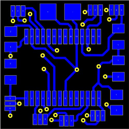
BOTTOM 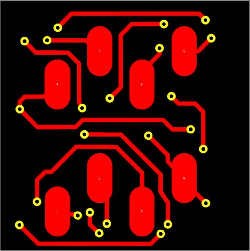
OVERLAY (No text yet) 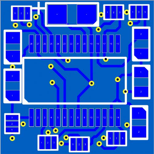
TABLE of link options 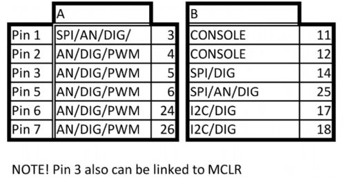
NOTE!! There are two link options for each pin (6 in total) plus Pin 3 can be sub linked to MCLR for programming so pins 2,3 & 4 are a pseudo ICSP header. Regards, Mick Mick's uMite Stuff can be found >>> HERE (Kindly hosted by Dontronics) <<< |
||||
| bigmik Guru Joined: 20/06/2011 Location: AustraliaPosts: 2981 |
Lads, Further NOTEs for MuP-Mini 
I have also used those SMT header pins on the bottom layer for connectivity to a standard 0.3" 8 Pin DIP IC socket Mick EDIT as I said this board is TINY, you can get 9 on a 50mm x50mm PCB. but some track clearances are down to about 0.007" Mick Mick's uMite Stuff can be found >>> HERE (Kindly hosted by Dontronics) <<< |
||||
| Zonker Guru Joined: 18/08/2012 Location: United StatesPosts: 772 |
Nice..! I like this stuff... Awesome layouts Gent's I think the SSOP on a 28pin DIP socket pattern (600) wide. Add in a 3.3v regulator, the DFN12 FTDI USB console port and PicKit-3 programmer port. Might be fun... |
||||
| Grogster Admin Group Joined: 31/12/2012 Location: New ZealandPosts: 9975 |
Wow, Mick - you the man!  
...but weren't you supposed to be enjoying your birthday?(rhetorical) That is fantastic layout-ing. I have just not had the doube-sided experience yet, to think quite along those lines. But I will in time.
With the clearances being that tight, do you think PCB houses like iTead will still accept a board that is so tight? Smoke makes things work. When the smoke gets out, it stops! |
||||
| bigmik Guru Joined: 20/06/2011 Location: AustraliaPosts: 2981 |
Hi Grogs, No I had a break yesterday... Most of that was done today.. I think it should be OK with PCB fabs.. I think most/all clearances are at least 0.2mm. I have sent off a preliminary artwork to SITOPWAY (my usual FAB house) for a quotation as 100 individual boards and also as a block of 3x3 Vee-Grooved to see if they can actually do them and what sort of price per unit they would be.. A moot point in a way as I dont know what sort of market there would be but I am pretty keen to play with a few.. it could open the door to some interesting projects with `multi-CPUs' for dedicated tasks. I am pretty happy with the size as it would plug into an 8 pin socket with 0.1" (2.5mm) overhang all 4 sides. I will keep you posted with quotes when/if they get back to me.. I would hope that we can get a `block' of 9 for sale at $3-$4 each which would work out at 35c or so per PCB that factors in freight costs and some beer for BigMik and any TBSers that wish pop over and help me consume it. Mick PS. The resistors and bypass caps are 0805 type which are pretty small. Mick Mick's uMite Stuff can be found >>> HERE (Kindly hosted by Dontronics) <<< |
||||
| bigmik Guru Joined: 20/06/2011 Location: AustraliaPosts: 2981 |
Lads, I don't suppose someone actually has an SSOP '170 do they? If so can someone put a vernier over the chip and measure its length for me please? I looked but I couldn't find a definitive size mentioned for the chip itself.. I found the pad footprint though.. Maybe I missed it in the 2 1/2 million pages of technical goop.. Mick Mick's uMite Stuff can be found >>> HERE (Kindly hosted by Dontronics) <<< |
||||
| WhiteWizzard Guru Joined: 05/04/2013 Location: United KingdomPosts: 2991 |
Mick, You know I'll always take a quantity of these to fund some 'beer' for you and your guests! Each Airmail Pigeon should be able to manage a decent quantity too! Any thoughts on PCB thickness? Would 0.8mm be too thin?? WW |
||||
| Grogster Admin Group Joined: 31/12/2012 Location: New ZealandPosts: 9975 |
Overall length is 10.2mm, according to the datasheet. Pages 299 and 300. Smoke makes things work. When the smoke gets out, it stops! |
||||
| WhiteWizzard Guru Joined: 05/04/2013 Location: United KingdomPosts: 2991 |
Mick SSOP (DS60001168F-page 299) length = 10.2mm +/-0.3 |
||||
| WhiteWizzard Guru Joined: 05/04/2013 Location: United KingdomPosts: 2991 |
I could always send you a DIL to SSOP adaptor board if thats any use  |
||||
| bigmik Guru Joined: 20/06/2011 Location: AustraliaPosts: 2981 |
Phil, I would think 0.5mm would be OK as there wouldnt be any real stress on the board.. I suppose that would be up to discussion.. and maybe dependent on any surcharges the FAB house wishes to add. Also thanks for your suggestions as to which pins to add.. I think I have come up with a pretty comprehensive `option-able' board (check the table I posted for more details) I can post a schematic but its pretty rough. Mick Mick's uMite Stuff can be found >>> HERE (Kindly hosted by Dontronics) <<< |
||||
| bigmik Guru Joined: 20/06/2011 Location: AustraliaPosts: 2981 |
Thanks Grog and Phil, I did see that in my earlier look, but I couldnt find it again when I designed the part for DEX.. I think I made the chip outline 10mm so I best check that there is sufficient space to fit the parts left and right of the PIC if it is 0.5mm longer than 10 then there `could' be 0.25mm extra length left and right. Mick Mick's uMite Stuff can be found >>> HERE (Kindly hosted by Dontronics) <<< |
||||
| Grogster Admin Group Joined: 31/12/2012 Location: New ZealandPosts: 9975 |
iTead charge nothing for PCB thickness from 1.0mm to 1.6mm. I always get thicker, as it is stronger, but that is just me, and for these little modules, thinner would probably be better. Interestingly, iTead can go down to 0.4mm thick, but it costs you more. Smoke makes things work. When the smoke gets out, it stops! |
||||
| bigmik Guru Joined: 20/06/2011 Location: AustraliaPosts: 2981 |
Lads, I just checked the artwork.. At the maximum length of 10.5mm the left hand side of the PIC would just butt the right hand side of the bypass and MCLR resistor so If we go ahead I would have to move these about 0.2mm to the left (should be sufficient). We could get away with it but there is a bit of room to move in that direction. Thanks for that. Mick EDIT *** There is room now for any `FAT' chips that we might run across.  Mick's uMite Stuff can be found >>> HERE (Kindly hosted by Dontronics) <<< |
||||
| MicroBlocks Guru Joined: 12/05/2012 Location: ThailandPosts: 2209 |
I am not sure about using smt type connectors. There is not much copper left that is bonded to the substrate to withstand the forces. Maybe increase the size (as big as possible) of the solder islands. You can also put in a small via in the island to get some extra strength. Microblocks. Build with logic. |
||||
| WhiteWizzard Guru Joined: 05/04/2013 Location: United KingdomPosts: 2991 |
Agree with TZA; and to add to that, I would also go for the thickest copper pour option. |
||||
| The Back Shed's forum code is written, and hosted, in Australia. | © JAQ Software 2026 |
